How to Convert Modbus to IEC104
IEC 60870-5-104 protocol is widely used in the electric power industry, Users can use the SCADA system to monitor and control processes remotely. But in a real environment, the power meters usually use Modbus RTU protocol. Hence, users need to use a gateway to convert Modbus to IEC 104 to suit monitoring and controlling purposes. This document will tell you how to set up Bivocom Gateway as an IEC 104 Server and Client.
What is IEC 104
IEC 60870-5-104 (IEC 104) is an international standard for communication protocols used in the utility automation industry, particularly in power systems. It defines the rules for exchanging data between control systems and devices like Remote Terminal Units (RTUs) and Intelligent Electronic Devices (IEDs) over TCP/IP networks. This protocol allows for real-time monitoring and control of power system equipment, ensuring efficient and reliable operation.
What is Modbus RTU/TCP?
Modbus RTU and Modbus TCP are two variants of the Modbus protocol commonly used in industrial automation and control systems. While Modbus RTU is more commonly used in legacy systems with serial communication interfaces, Modbus TCP has become increasingly popular due to the ubiquity of Ethernet networks in industrial environments. Both variants provide reliable and efficient communication for industrial automation applications.
What do you need?
A Bivocom gateway, SCADA Software support IEC 60870-5-104 Protocol(IEC 60870 Test Master), RS485 Wire, a Network cable, and USB-RS485 Adapter.
How to convert Modbus to IEC 104?
- Bivocom Gateway Works as IEC104 Master(Client) Mode
- Data Collect
- Basic Setting
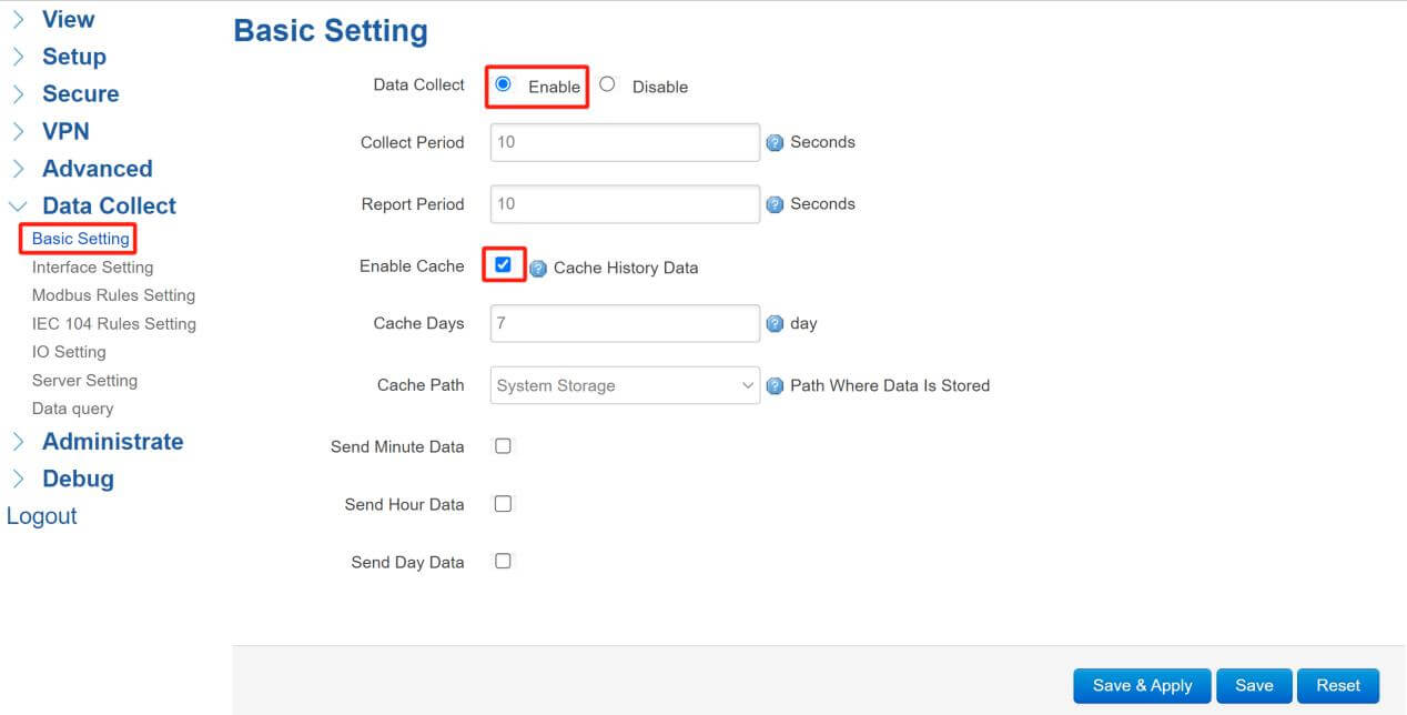
Enter the “Data Collect” menu, click the “Enable” button, and select “Enable Cache”. Then click “Save”.
- Interface Setting
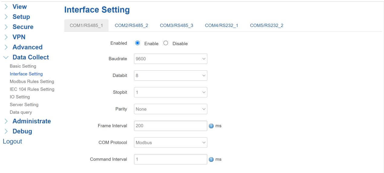
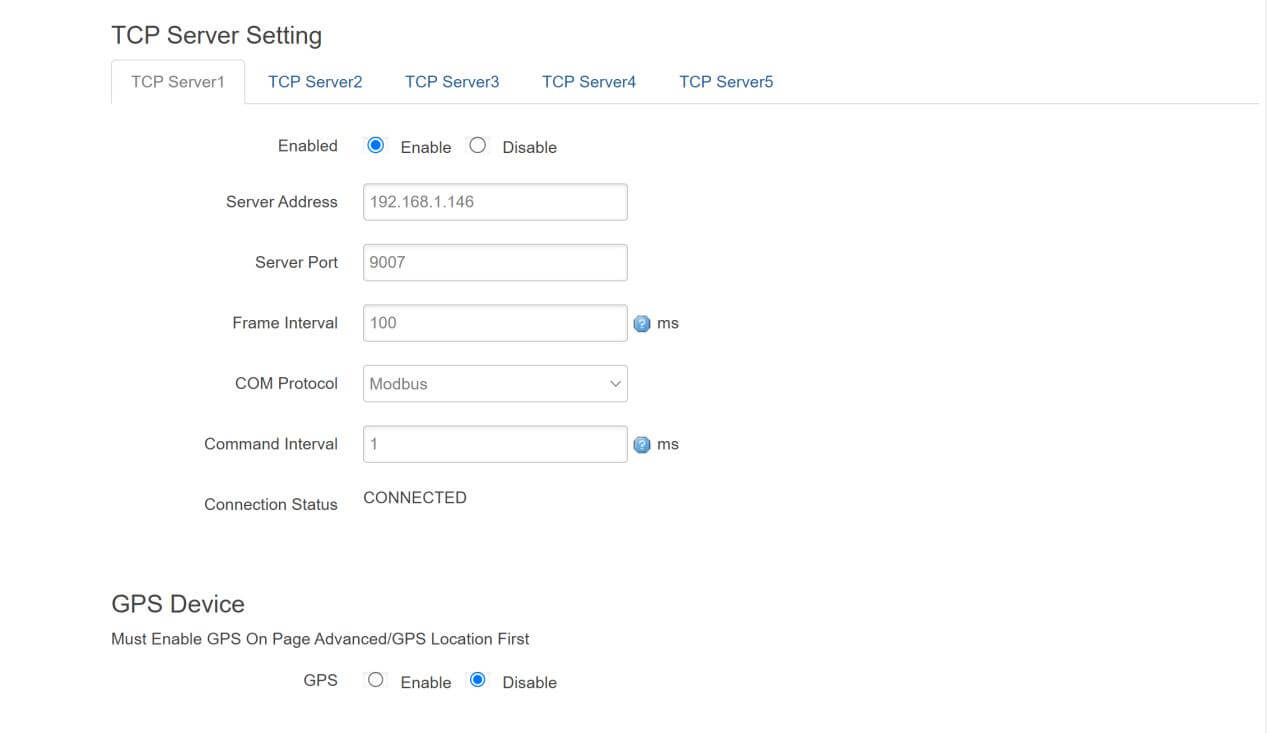
Come to the “Interface Setting” page, set up the COM port and TCP port, in this document we use the RS485-1 port, here we need to set the right TCP address and port of the Modbus TCP slave device.
- Modbus Rules Setting
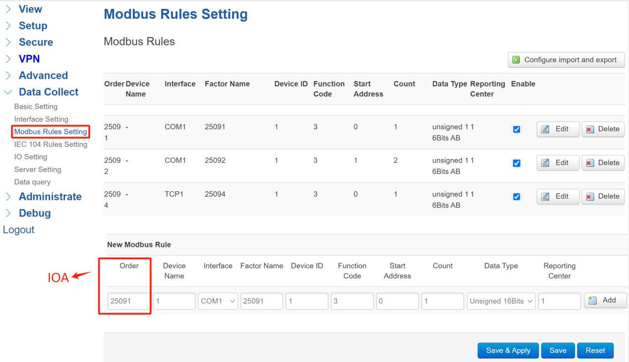
Click “Modbus Rules Setting” to enter the rules setting page, setup “new Modbus Rule”, “Order” stands for IOA, and “Device Name” can be set as you wish, you will need to choose the “Interface” of power meter connected, “Factor Name” is the name of Modbus data, it can be set what you want, “Device ID” needs to follow the power meter’s datasheet, “Function Code” here we set it as “3”, “Start Address” and “Count” also regulated by power meter. “Reporting Center” corresponding to the server number. After setup, click the “Add” button, then click “Save”. Then set up Modbus TCP Rule following the above format.
- IO Setting
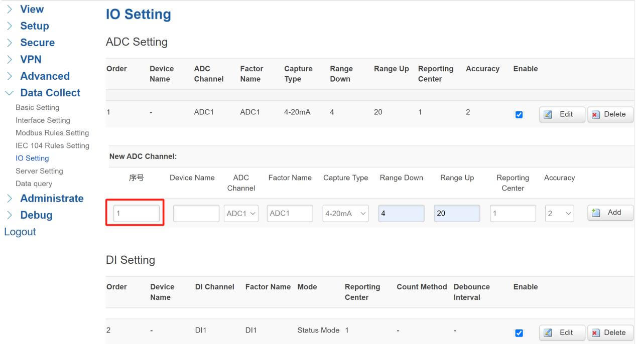
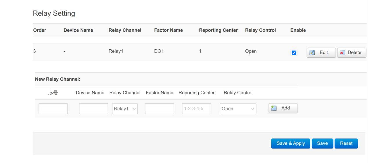
Click “IO Setting” to set up ADC, DI and Relay. Add a new ADC channel by typing the “Order” number, it will be the IOA of this data too, here we set the ADC Order name as “1”, DI Order as “2”, and Relay Order “3”.
Notice that ADC and Relay will be transmitted to IEC 104 with “M_ME_TF_1”(Short floating point telemetry with quality description with absolute time scale), DI will be “M_SP_TB_1”(Single point remote message with quality description and absolute time scale).
- Server Setting
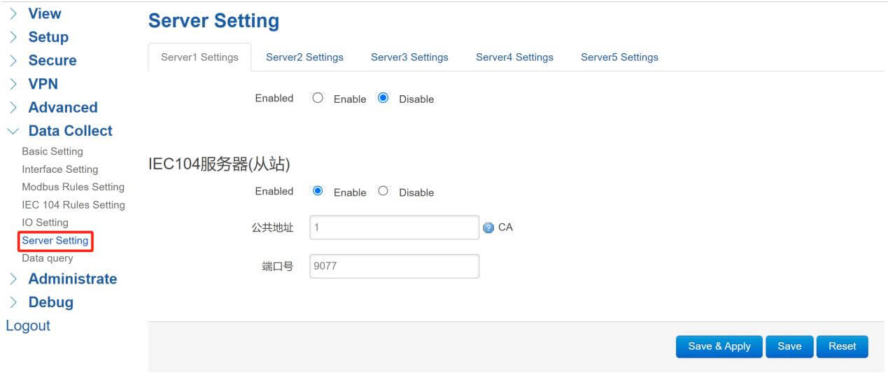
Come to the “Server Setting” page, here we can set the IEC104 Client, and click “Enable” to open IEC 104 Client, “CA” stands for Common Address, it is the CA address of SCADA connects, we set “1” at this case. “Port” here I set it “9077”.
- Modbus RTU/TCP Simulator
- Modbus Slave
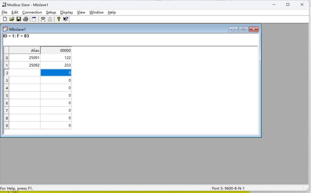
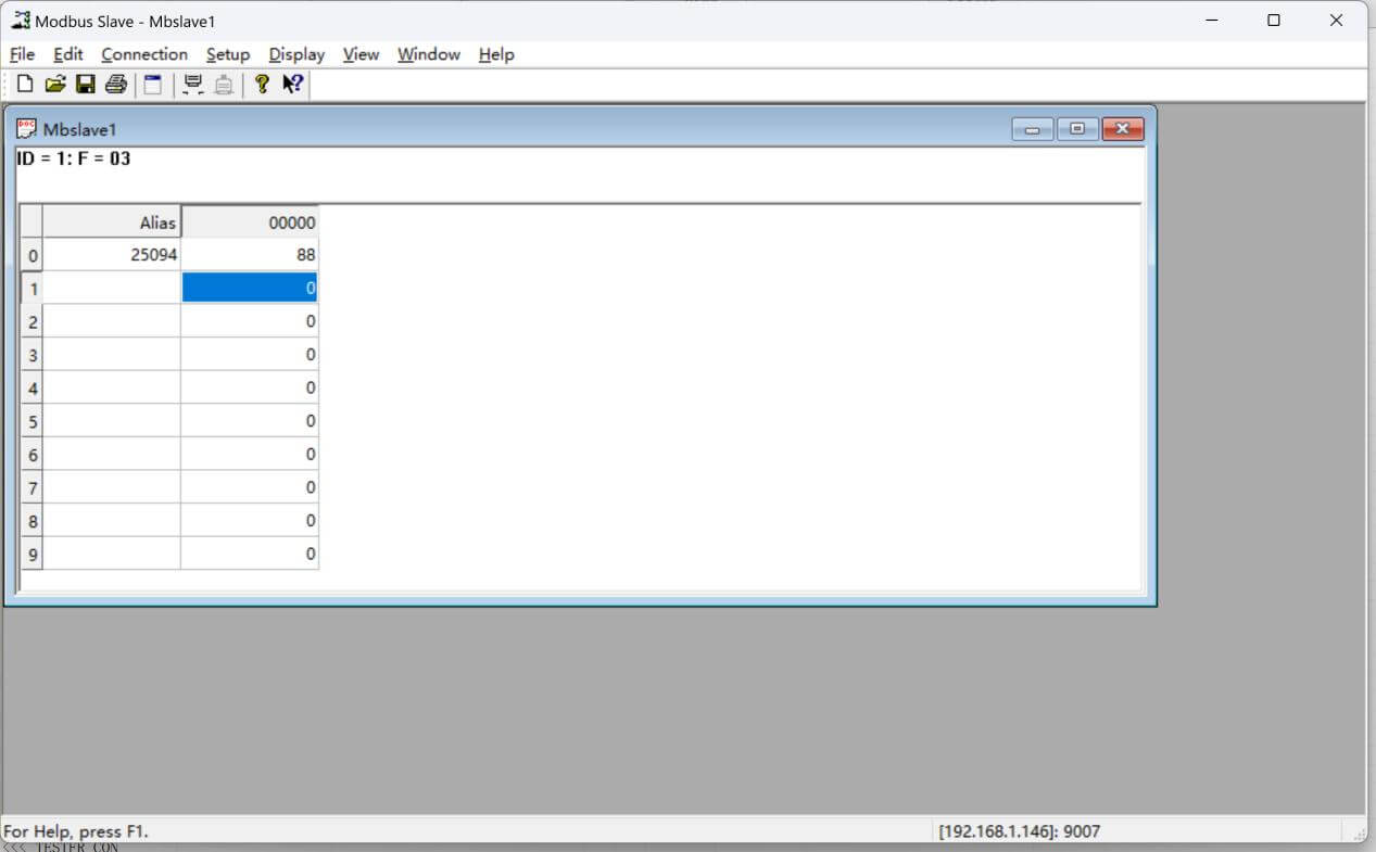
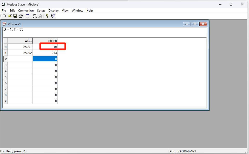
In this document, I use Modbus Slave to simulate Modbus RTU/TCP meters. Open “Modubs Slave”, set up the connection with Bivocom gateway, and then type the data in the data boxes. In this case, I will set up both Modbus RTU and TCP data simulator.
Modbus RTU:
Modbus TCP:
- IEC 60870 Test Tool
- Setup connection
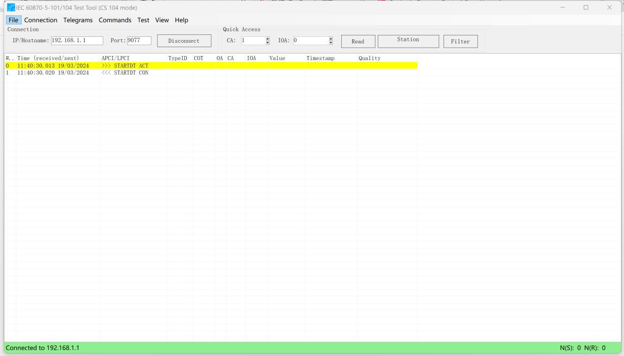
Open the IEC 60870 Test Tool, and type the “IP/Hostname” and “Port”, in this case, we need to set “192.168.1.1:9077”, and “CA” here we set it as “1”. After settings, click “Connect” button.

It will show “Connected to 192.168.1.1” if the connection was built.
- Read Data
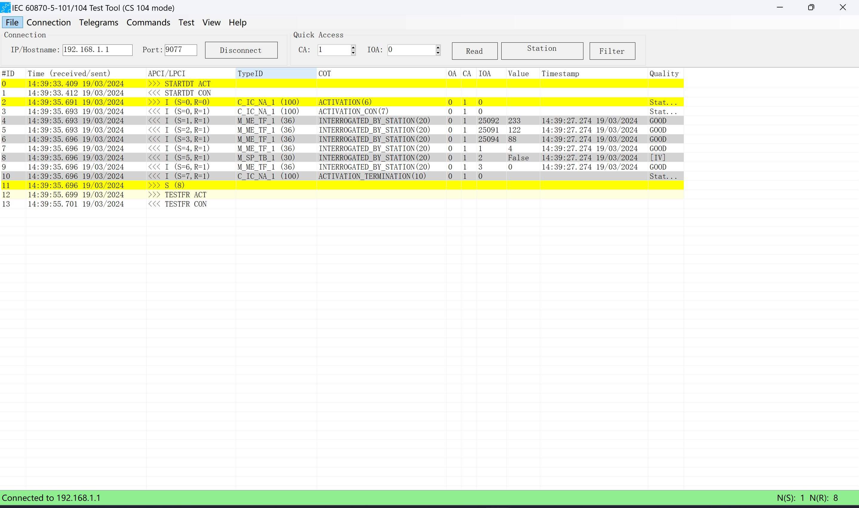
After the connection was built, we can click the “Station” button to get data from Modbus meters. At the log bar we can check the “TypeID”, Modbus RTU, Modbus TCP, ADC and Relay data are transmitted as “M_ME_TF_1”, DI data will be “M_SP_TB_1”. We can also check the “Value” with “Timestamp”, the data will be transmitted with “Quality” too.
- Write Modbus Data&Convert to Remote Time Zone
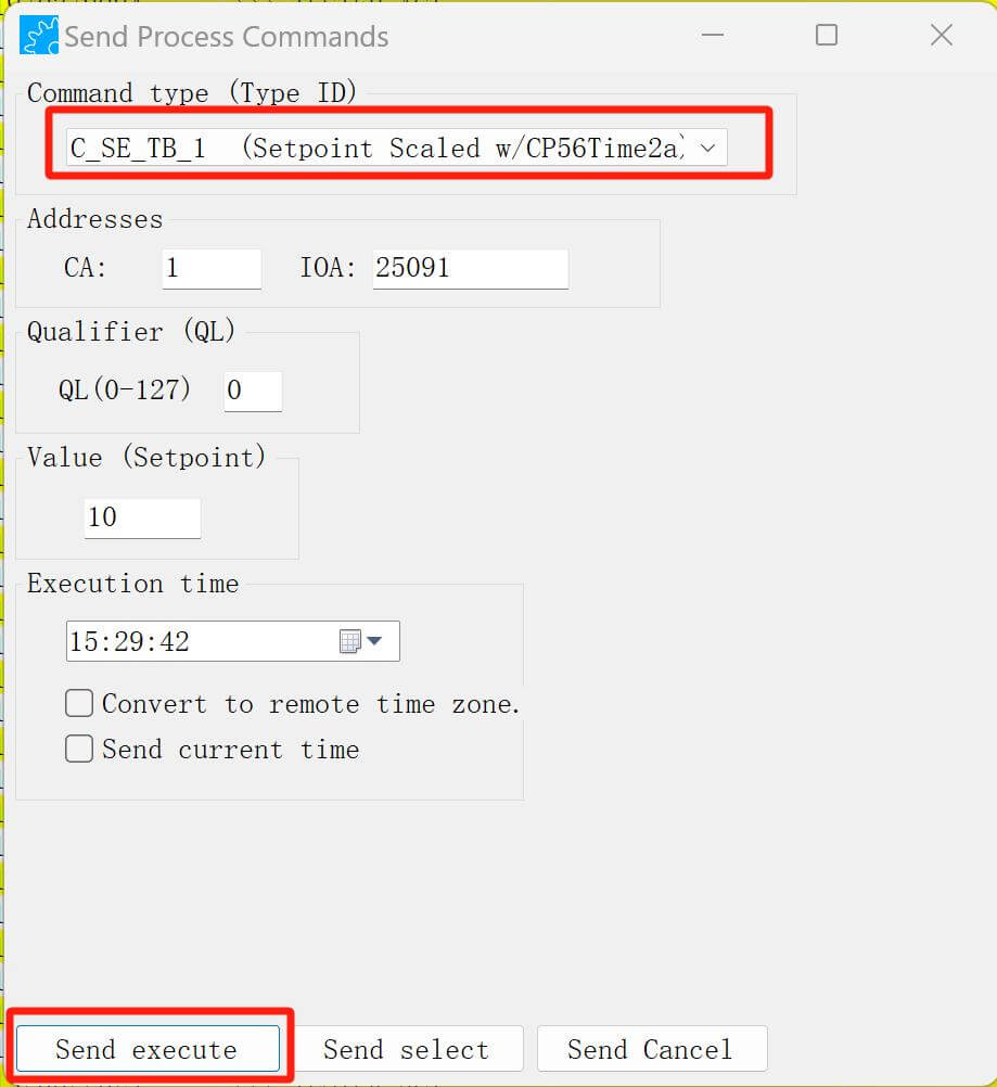
Bivocom Gateway can support sending IEC 104 server commands to change the parameter of Modbus registers and also can change the remote time zone. Here are the steps:
- Click “Commands” to enter the command sending function, select “Command type” as “C_SE_TB_1”, enter the CA address and IOA, “Qualifier”(QL) here I set “0”, and set the “Value” as you wish, then click “Send execute”.
- Convert to remote time zone
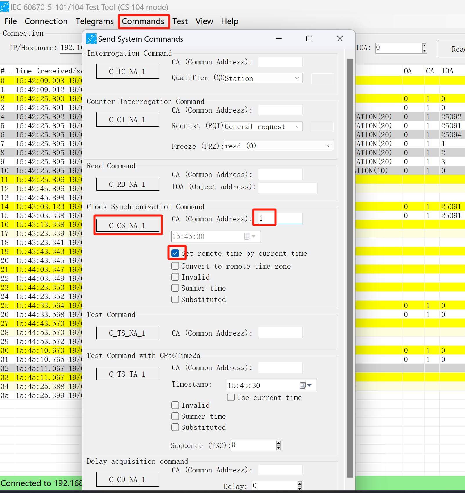
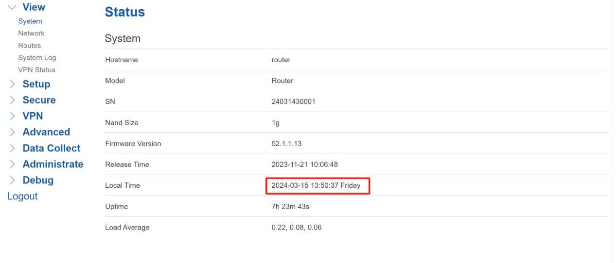
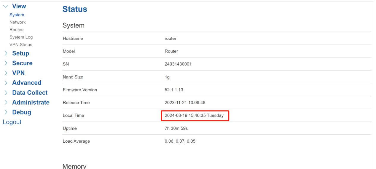
Bivocom Gateway supports the SCADA System to send current time convert to remote. In this case, we will use the “Send System Commands” function, click the “Commands” menu to enter, and then select “Set Remote time by current time”. “CA” set as “1”, then click the “C_CS_NA_1” button to execute the command.
Before executing command:
After executed:
- Bivocom Gateway Works as IEC104 Slave(Server) Mode
- Data Collect
- Basic Setting
The same as Master(Client) Mode, we enter the “Data Collect” menu, click the “Enable” button, and select “Enable Cache”. Then click “Save”.
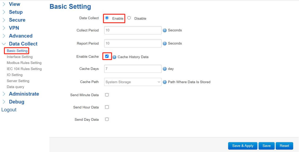
- Interface Setting
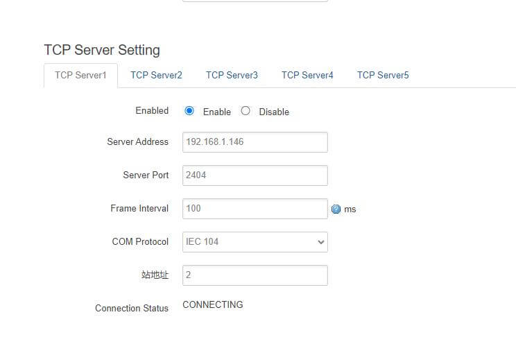
Different from Master(Client) Mode, the IEC104 device should be connected to the “TCP Server”. Enter the “Server Address” which is connected with Bivocom Gateway, set up “Server Port”, select “COM Protocol” as “IEC104”, and the “CA” common address here we set as “2”. After connecting successfully, we can see the “Connection Status” changed to “CONNECTED”. Please check the details at the screenshot:
- IEC 104 Rules Setting
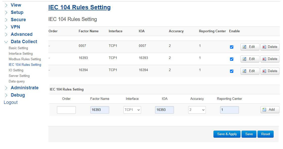
Come to the “IEC 104 Rules Setting” page, enter the “Factor Name”, select “Interface” as “TCP1”, “IOA” should follow the IEC104 Simulator device, choose “Accuracy” as you wish, and set “Reporting Center” to “1”. After setup, click “Save&Apply”. Check the details below:
- Simulate IEC 104 Server
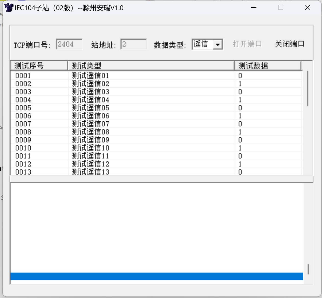
Here I use software to simulate the IEC 104 Server, change the CA address to “2”, and select port “2404” the same as the TCP server setting.
- Data Query
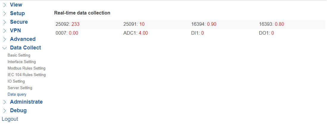
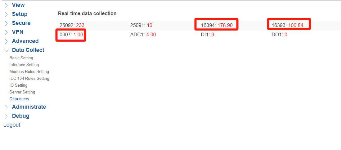
After connecting successfully, we can check the data at the “Data Query” page, here can see the changes of each factors, if the value of the corresponding IOA in the Simulator has been changed, we can also find the changes here.
Before changing value:
After changing the values:
- IEC 60870 Test Tool
- Setup connection
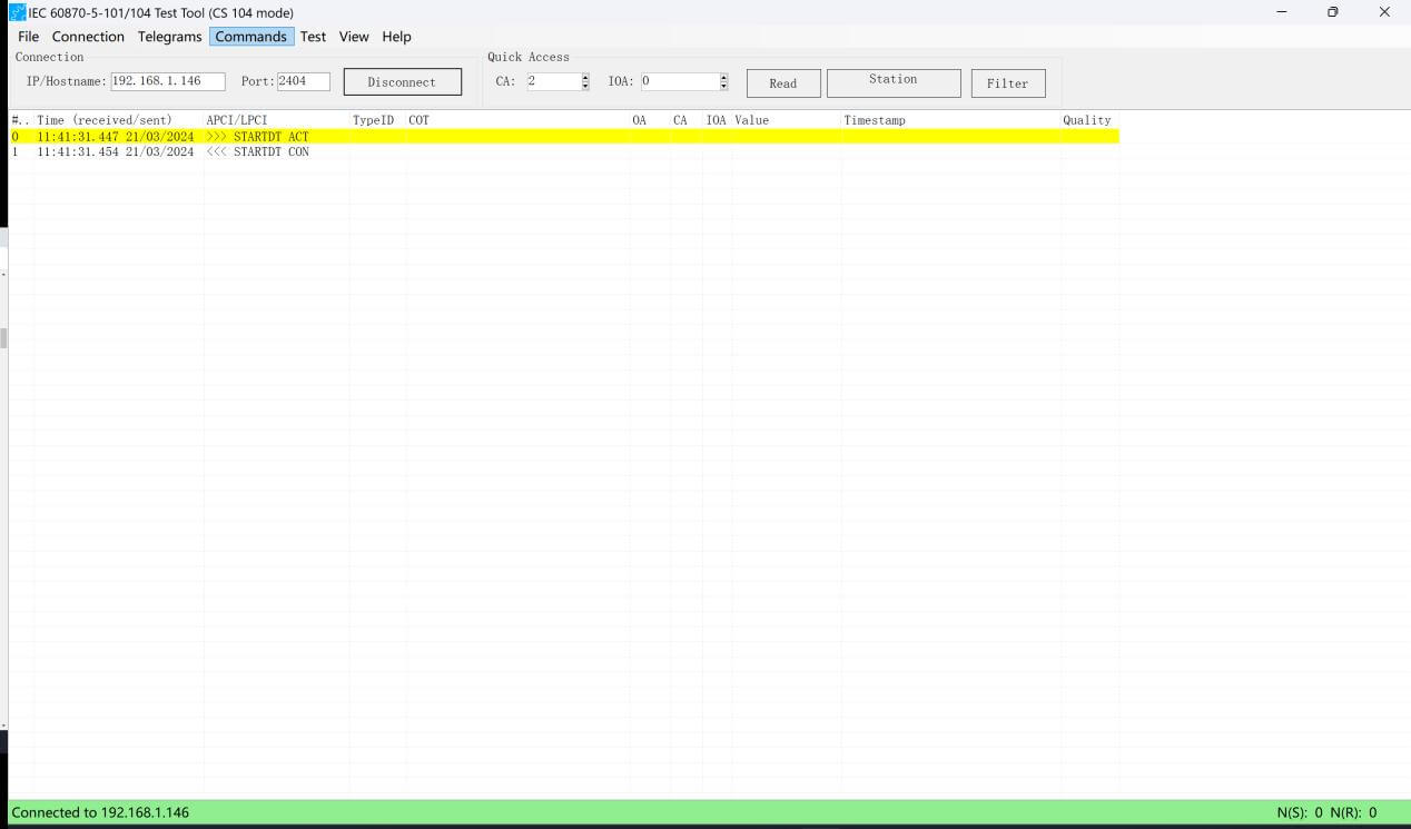
Open the IEC 60870 Test Tool, and type the “IP/Hostname” and “Port”, in this case, we need to set “192.168.1.146:2404”, and “CA” here we set it as “2”. After settings, click the “Connect” button.
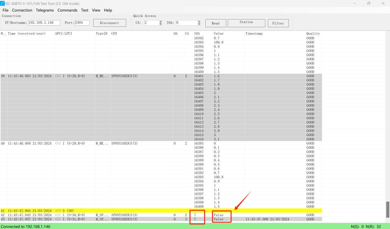
It will show “Connected to 192.168.1.146” if the connection was built. The values will be reported to here automatically.
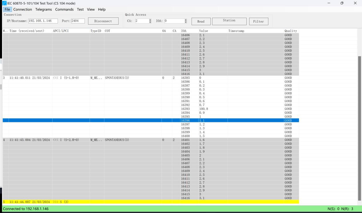
If the value of telesignalisation was changed, it will report for the first time:
That is a quick guide of how to convert Modbus RTU/TCP to IEC 104 via Bivocom IoT Gateways/Routers.
Banner image from :https://www.pexels.com/zh-cn/photo/236089/




Comment