In this article, we’re going to tell you how to connect your IoT routers or gateways to Bivocom IoT platform.
1. What You Need?
- Bivocom IoT Router or Gateway
TR321, TR341, TG451, TG452, TG462(S), TG453, TG463
- Bivocom IoT Platform Demo
Bivocom provides customizable web page based IoT platform with on premise service. The platform is able to receive real time data from field sensors or equipment under Modbus rules/TCP, converted them to JSON and transfer via MQTT over cellular network, such as 5G/4G.
To learn more about Bivocom routers, gateways and IoT platform, please contact Bivocom team at [email protected], or [email protected]
Let’s get started.
2. Bivocom Router Setting
1) Enable Data Collect
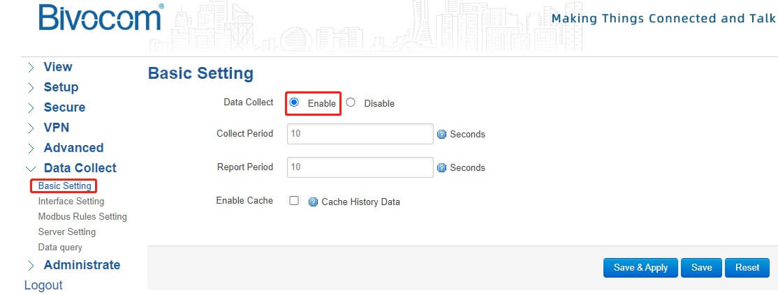
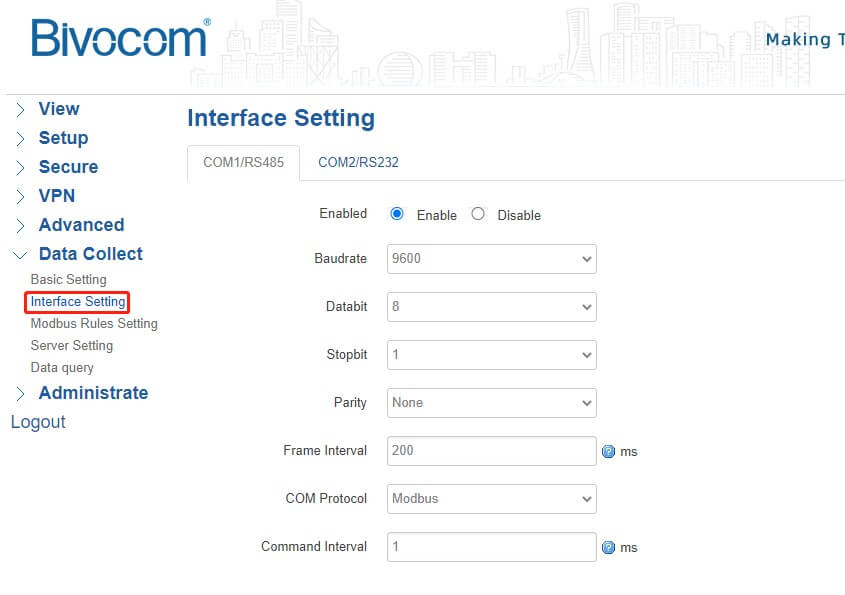
2) Setup the corresponding Interfaces same as the slave devices, such as temperature, humidity, water level, water quality sensors, etc.
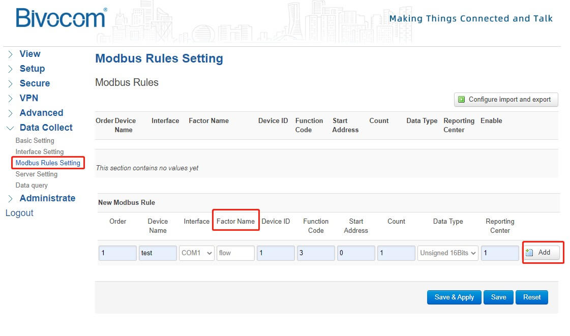
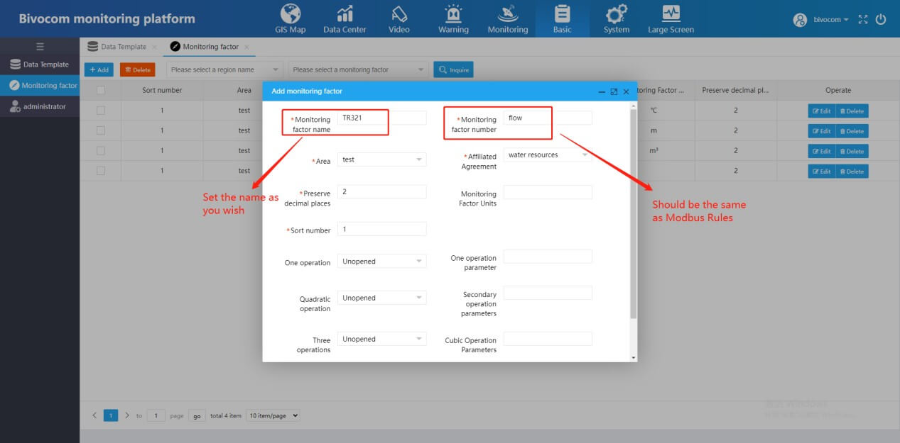
3) Setup the Modbus Rules. Please note that the Factor Name is also the Monitoring factor number of the IoT platform.
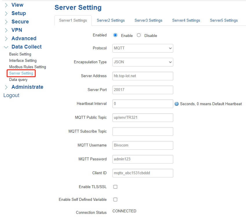
4) Server Setting: Set the server address as hb.top-iot.net, and server port as 20017. The MQTT Public Topic should be set as up/env/***. Notice *** should be setup the same as the Monitoring factor name at the platform.
MQTT Username: Bivocom
MQTT Password: admin123
After above settings of IoT routers or gateways completed, we can go to next step-setting up the Bivocom IoT platform.
2. Bivocom IoT Platform Setting
1) Login platform: http://hb.top-iot.net:20016/
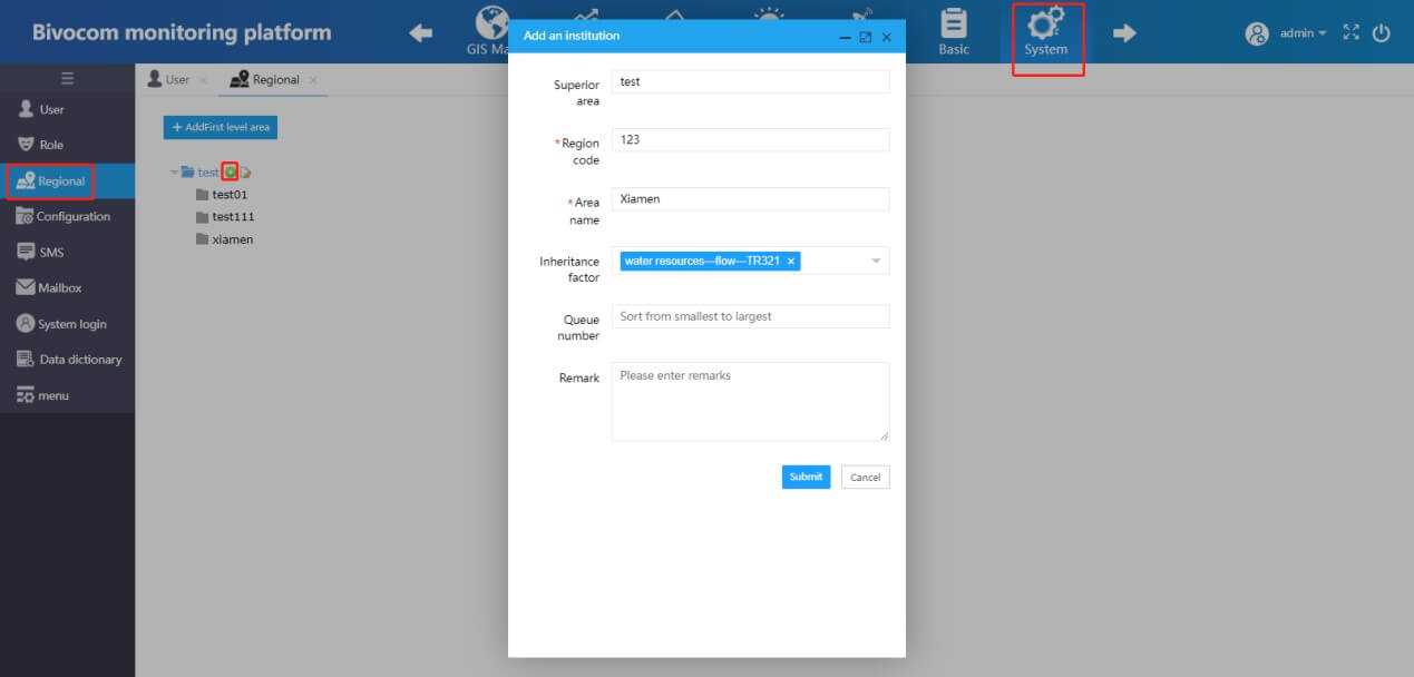
2) Add another area: Region code should be unique, and you can setup Area name as you want.
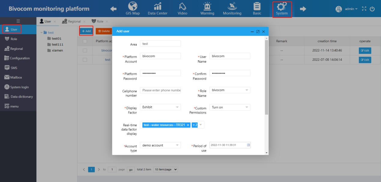
3) Add another user and setup the other settings.
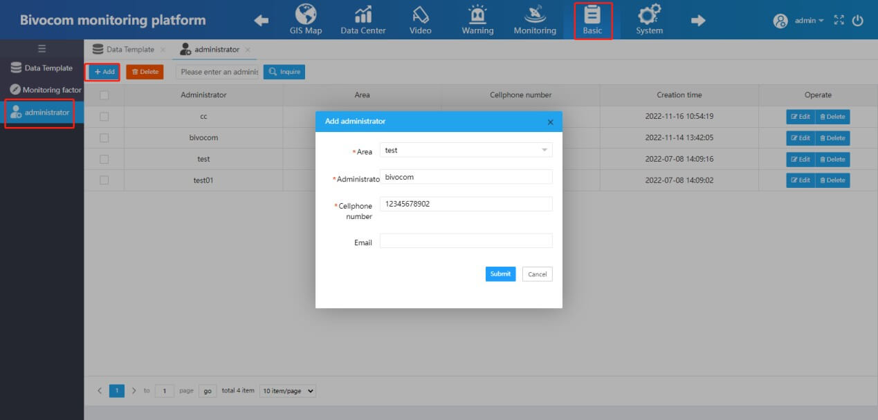
4) Administrator settings: Setup another Administrator.
5) Monitoring Factor settings: Set up the Monitoring factor name you want, in this case, we set it as TR321. Monitoring factor number should be the same as Factor Name of Modbus rule in step 1 above. Monitoring Factor Units can be set as you need.
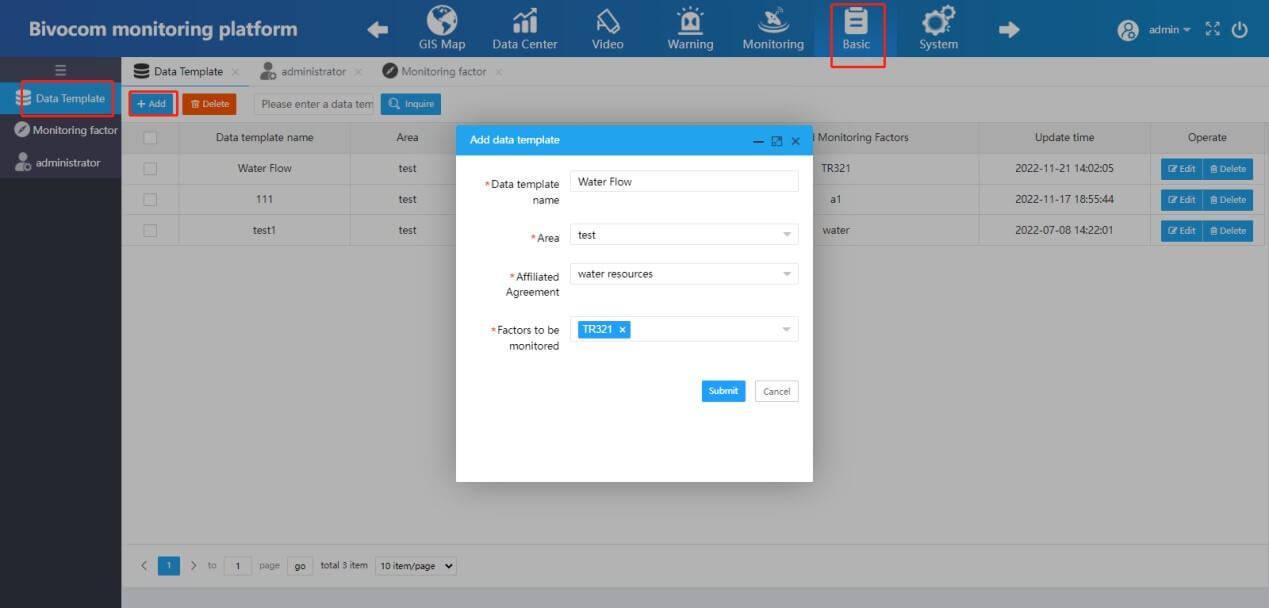
6) Data Template: Add a new data template, chose the corresponding area. You are able to add multiple factors (from the same device) to monitor.
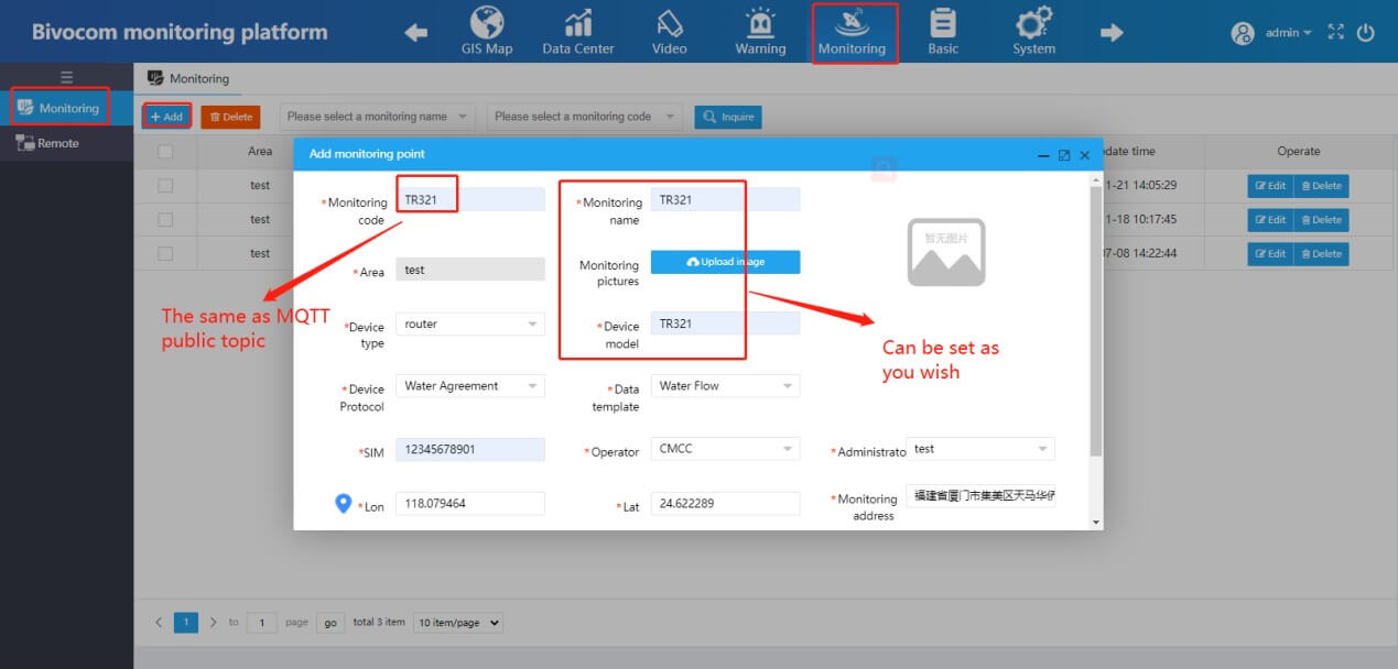
7) Monitoring code should be the same as MQTT Public Topic, in this case, we set it as TR321. Fill in the other required parameters and chose a coordinate of the device.
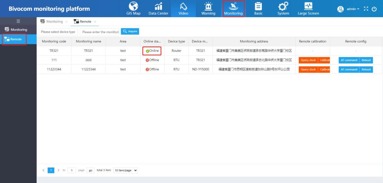
8) After settings, we can see the device status at Remote of Monitoring changed as online.
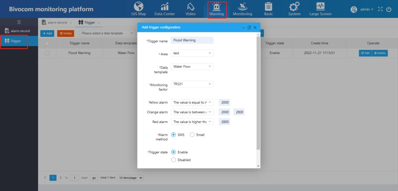
9) Warning settings: Add trigger configuration, set the Yellow, Orange and Red alarm as you want.
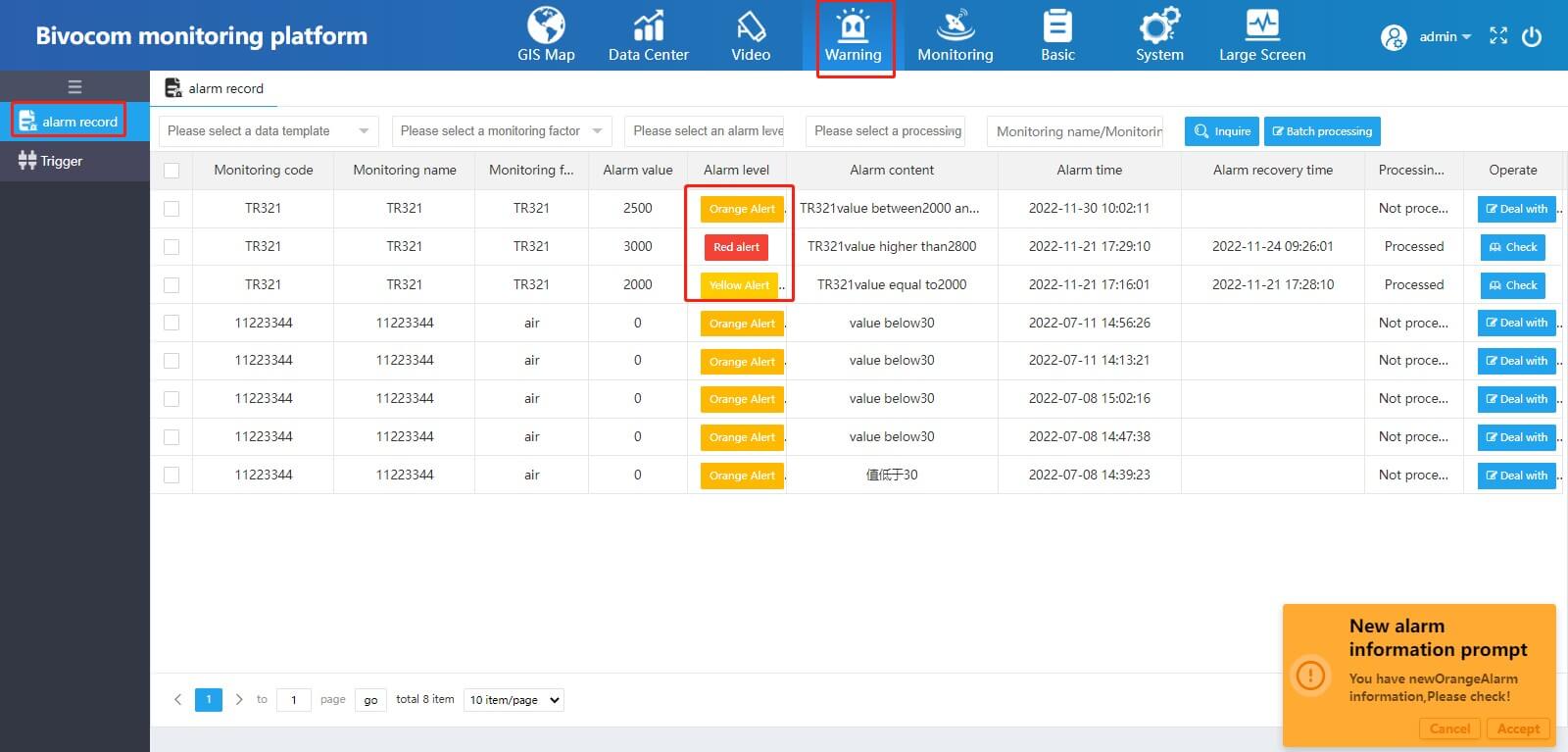
10) At the Alarm Record, we can see different level of alarm.
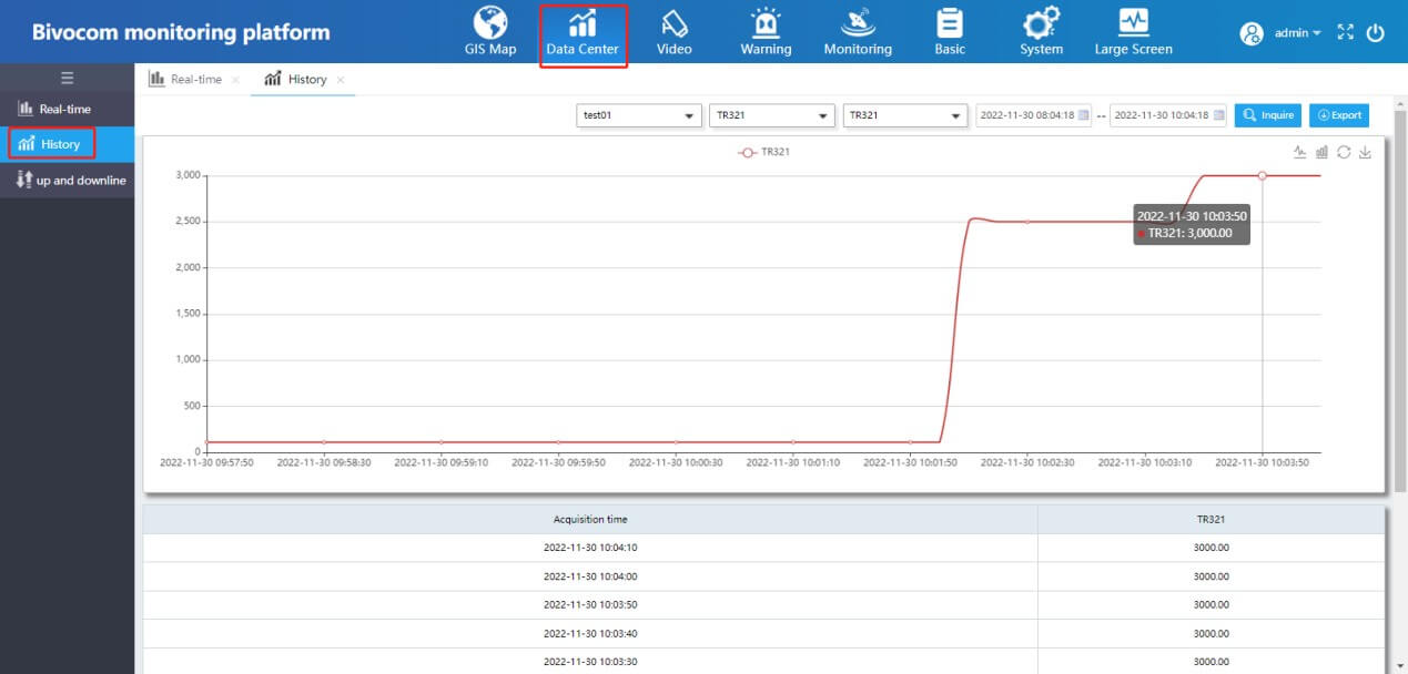
11) At Data Center, we can see the real time data of TR321. Besides, the Alarm will be sent to you via SMS or email.
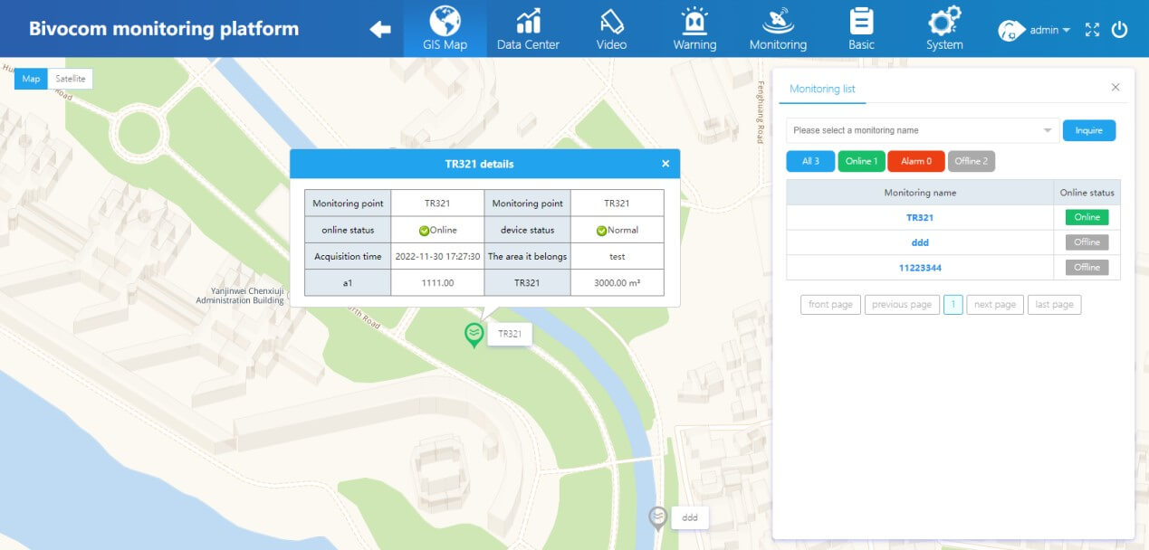
12) At GIS Map, we can see the status and location of devices.
4. Conclusions
The above quick guide shows you how to configure the IoT routers or gateways with Modbus protocols and transfer the data to IoT platform via MQTT, and users can get real time data from field sensors and get alarm via SMS or email from IoT platform.


Comment