In this article, I will use the MQTT Protocol to simulate the process of data collection and reporting through the publish/subscribe model on an industrial IoT gateway. The guide also tells you how to configure transparent data transmission and Modbus RTU, Modbus TCP on serial ports, IO(digital input, relay output), convert data to JSON, transfer it via MQTT over the cellular network, which is used to remote monitor the field data and control the field devices via relay.
- MQTT Introduction
MQTT is a lightweight messaging protocol based on publish/subscribe model, specifically designed for IOT applications in low bandwidth and unstable network environments. It can provide real-time reliable messaging services for network-connected devices with minimal code. MQTT protocol is widely used in IOT, Mobile Internet, Smart Hardware, Internet of Vehicles, Smart Cities, Power, Oil, Energy, and other fields.
- Transparent Test
Before the formal configuration, we can start with a transparent test to ensure the network connection between the client and server is normal, and understand the basic network environment through the test. The steps are as follows:
- Enter the WEBUI of configuration, then click the Basic Setting, enable the “Data Collect” feature, and set the Collect Period, Report Period, and other related options as you wish.
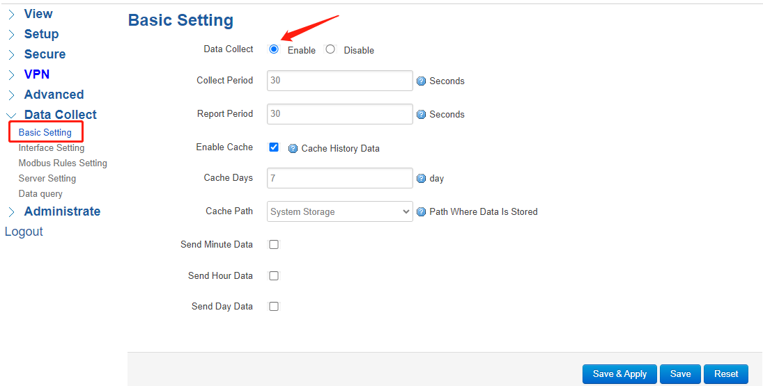
Data Collect: Enable or Disable the data collection feature, this is the switch of the whole data collection function
Collect Period: Set the period of data acquired from slave devices.
Report Period: Set the Period of data report to the server.
Enable Cache: Enable or Disable history data cache feature.
Cache Path: Choose where the cache data is stored.
Send minute, hour, and day data: Set the minute data period as you wish.
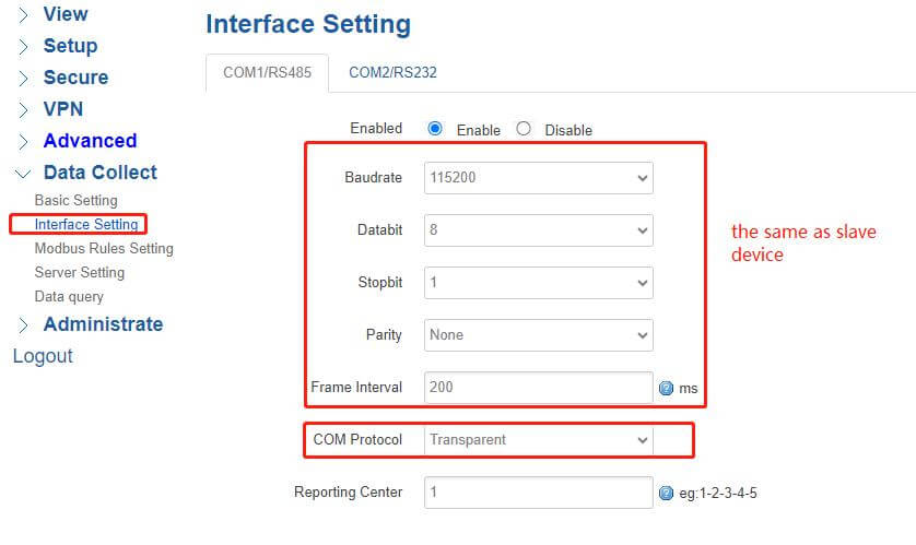
(2)Click the Interface Setting, and change the COM Protocol to “Transparent”, the other options must be set the same as a slave device.
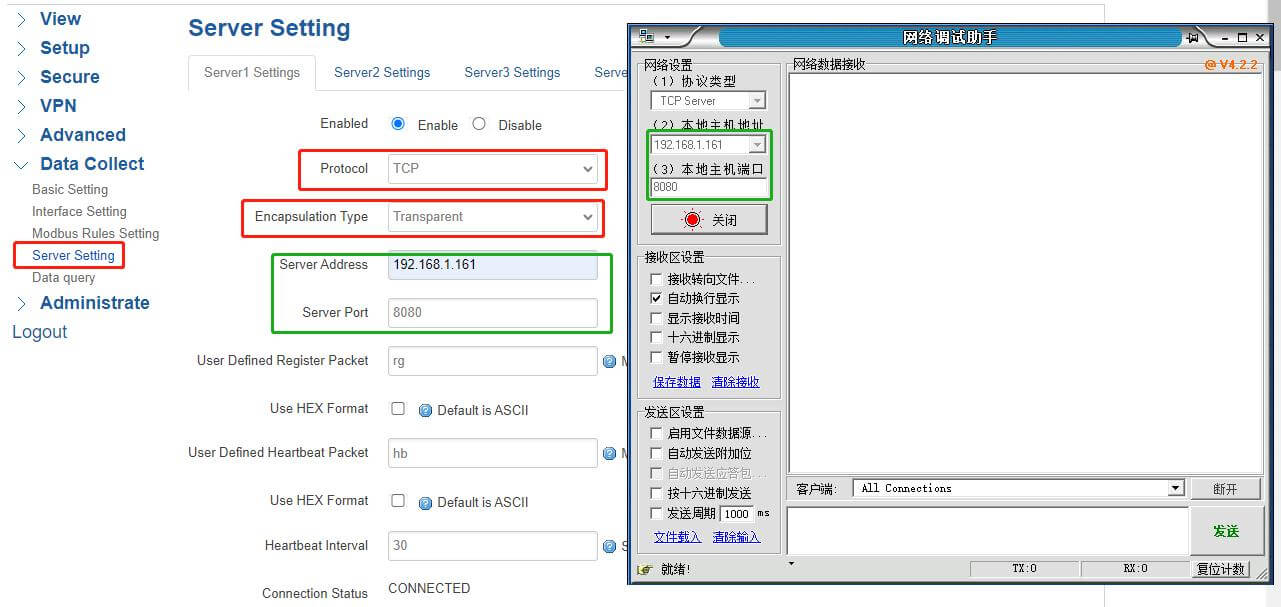
(3)Click the Server Setting, Protocol select “TCP”, Encapsulation Type select “Transparent”, the “Server Address” and “Server Port” must be set the same as the TCP server. The Register Packet, Heartbeat Packet, and Heartbeat Interval can be set as you wish.
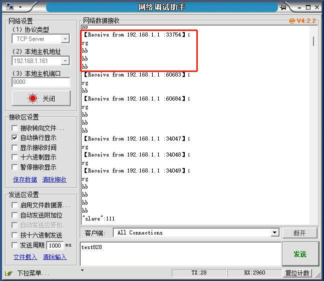
(4)Open the serial port tool, and open the specific serial port, then you can send any characters to the server.
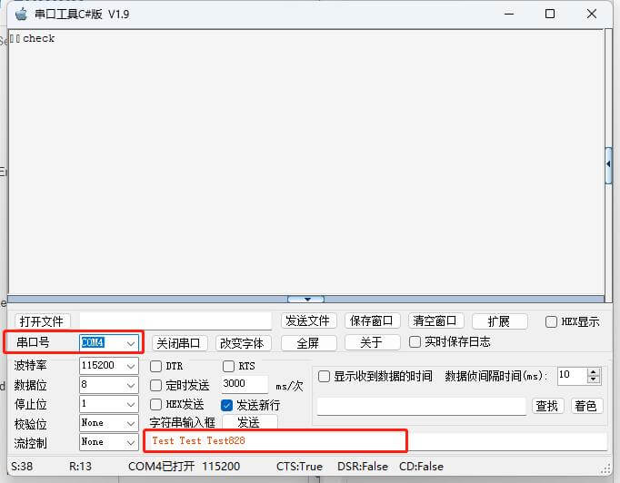
Then the TCP server will receive the message from the client, and you can also send a message to the client.
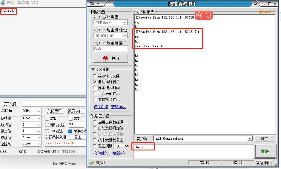
So far, the transparent test has been done, the data is being transmitted to each other, and then we can proceed next step.
- MQTT ClientConfiguration
- Data Collect ThroughModbus RTU
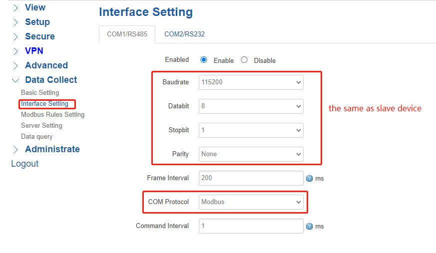
(1) Enter the WEBUI of configuration, and click Interface Setting, this time, I use an RS485 serial port to connect the router and PC, of course, you can choose RS232, and change the COM Protocol into “Modbus”, the other options must set the same as a slave device.
(2)Click Modbus Rules Setting, then add a new one. The Order, Device Name, and Factor Name can be set to whatever you want. The Device ID, Function Code, Start Address, and Count must be set the same as a slave device.
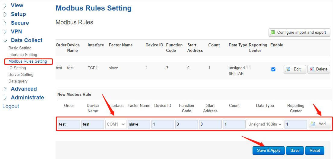
ATTENTION: You need to select the corresponding interface according to the specific serial port.
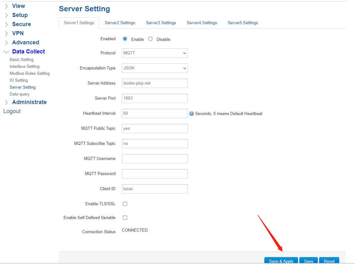
(3)Click Server Setting, the specific configurations are as follows:
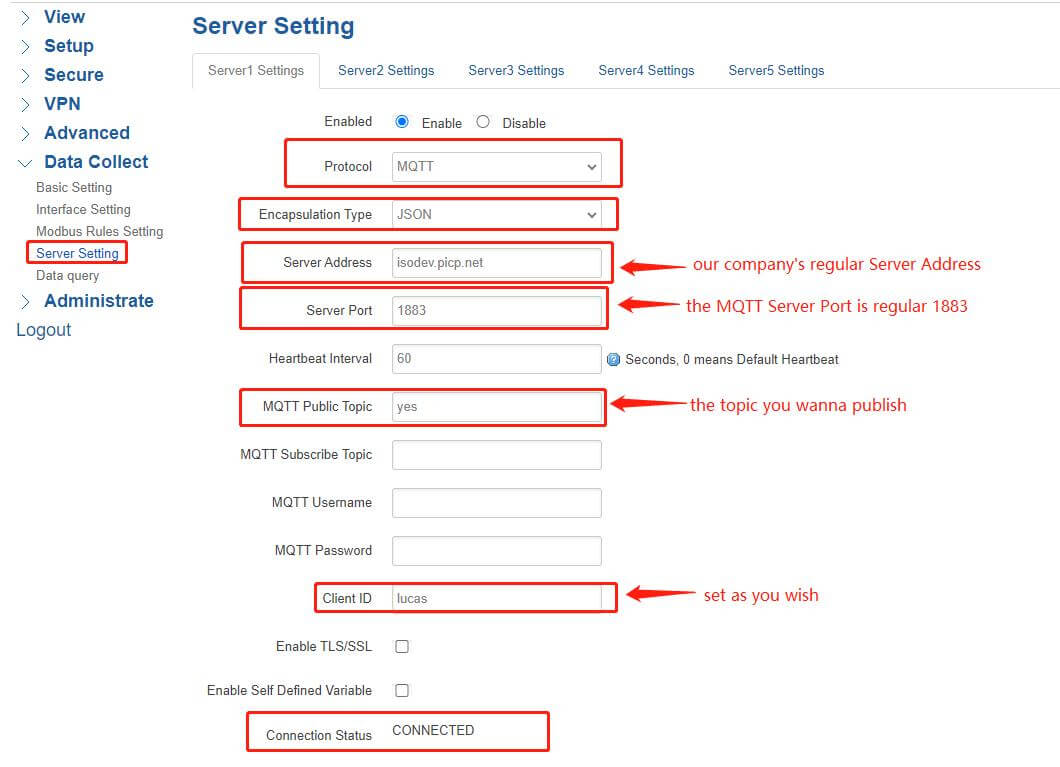
Protocol: Select “MQTT”
Encapsulation Type: Select “JSON”
Server Address: Bivocom has a regular address “isodev.picp.net”(for testing only)
Server Port:1883
Heartbeat Interval: the interval between data publication and subscription
MQTT Public Topic: the topic you wanna publish in the MQTT client
Client ID: Set a unique ID as you wish
After setting these parameters, remember to click “Save&Apply”, then the Connection Status will change to “CONNECTED”.
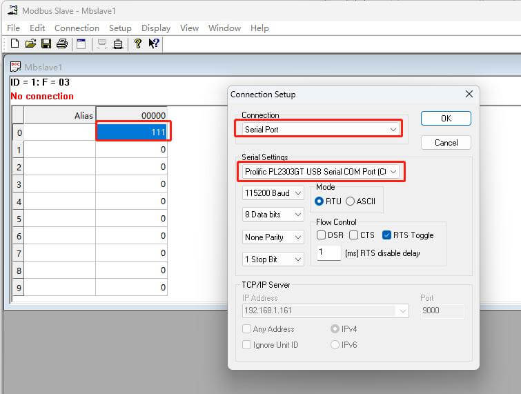
(4) Here I use Modbus Slave to simulate the slave device, open the simulate tool, set the corresponding interface parameters of the client router, and then click connect. In this case, I set the value as “111”.
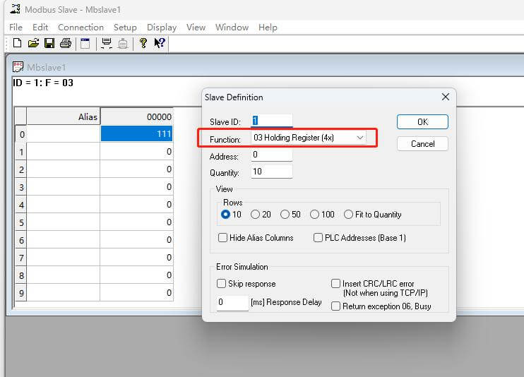
Open the Slave Definition, the Function code select “03” which means read the register’s data.
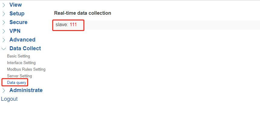
After setup, you can see the Real-time data collection accepts the value just set.
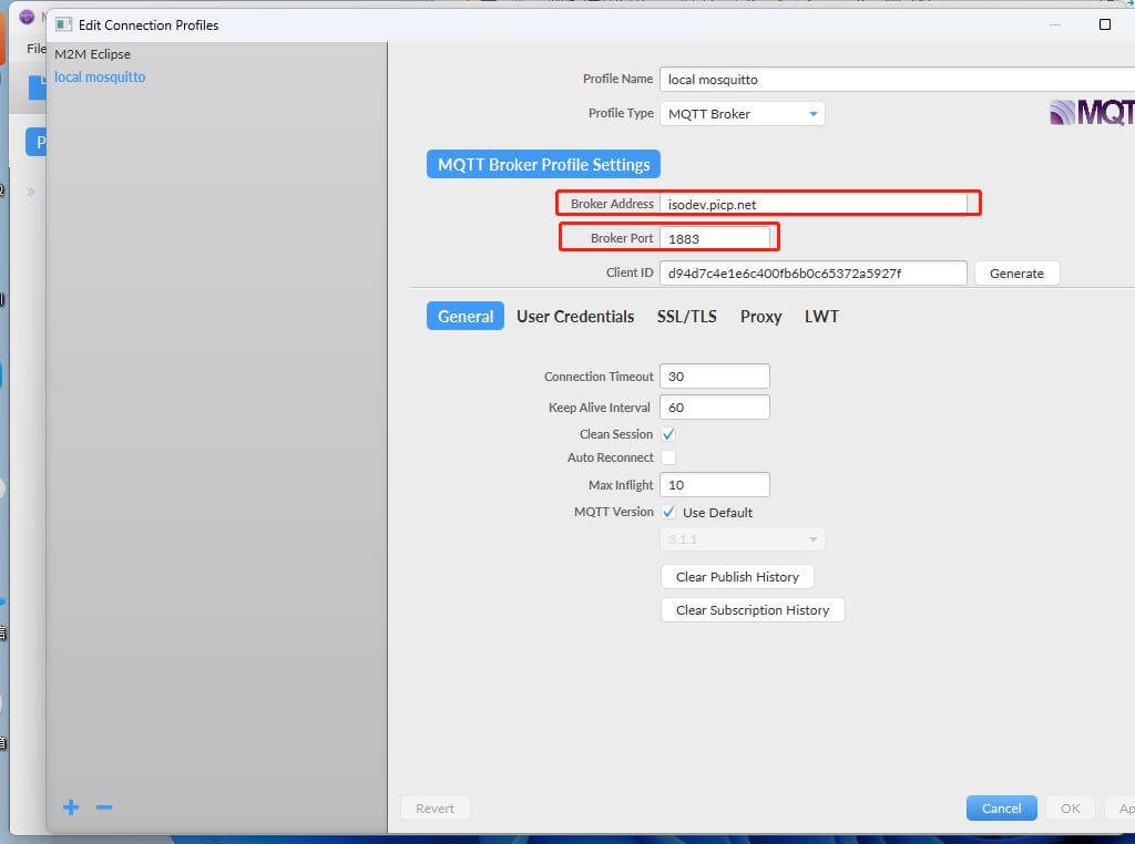
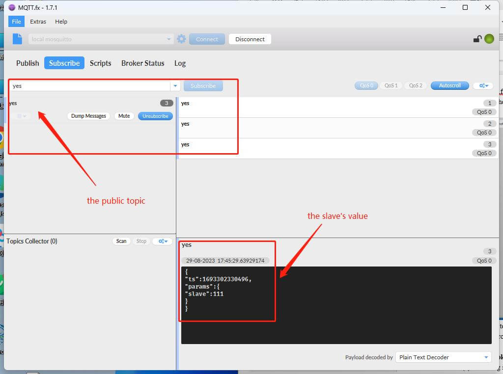
(5)Open the MQTT.fx tool or other software can work as an MQTT client on a PC, The Broker Address must be the same as the Server Address you just set, and the Broker port is also 1883. Finally, click connect after setup.
Then subscribe to the public topic I just set in the client server which is “yes”. There will be the topic message from the MQTT Client.
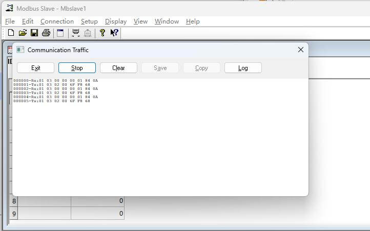
We can also see the communication between the slave device and the gateway.
- Data Collect Through Modbus TCP
The setting is almost the same as the ModBus RTU protocol, the interface is changed into RJ45 instead of a ModBus serial port. The specific steps are as follows:
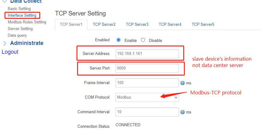
(1)Click Interface Setting, and enable the “TCP Server” option, The Server Address is the slave device’s IP address, COM Protocol select “Modbus-TCP”. The Server Port should be distinguished from the local TCP Server’s port, here I set as “9000”.
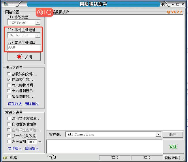
(2)Click Server Setting, the parameters are set as follows:
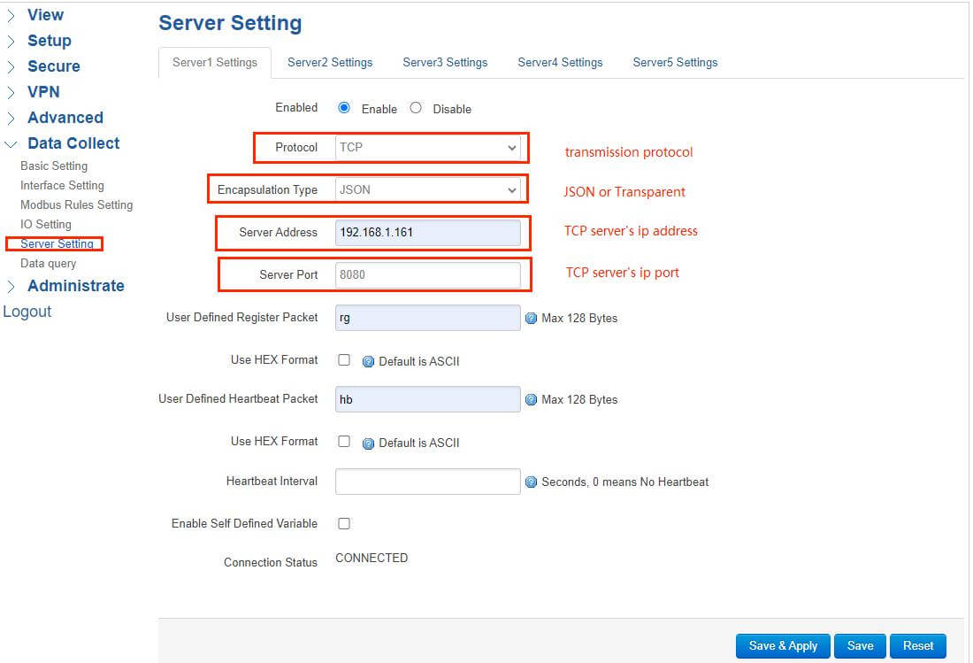
Protocol: Select “TCP”
Encapsulation Type: Select either JSON or Transparent
Server Address: the same as TCP Server “192.168.1.161”
Server Port: the same as TCP Server “8080”
After setting these parameters, remember to click “Save&Apply”, then the Connection Status will change to “CONNECTED”.
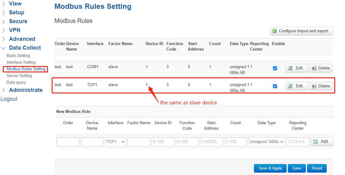
(3)Add a new Modbus Rule for the TCP interface, click ModBus Rules Setting, and select the interface as “TCP”, the other parameters are the same as COM.
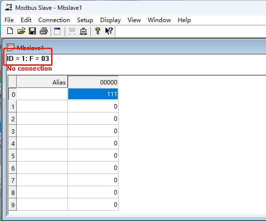
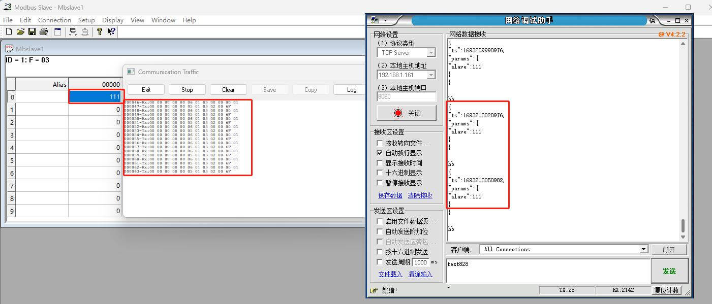
(4) Open the slave’s connection Setup, Connection selects “Modbus TCP/IP”, the IP address is the same as the TCP server. The slave’s port and TCP server’s port need to be distinguished, in order to ensure that a port is not occupied.
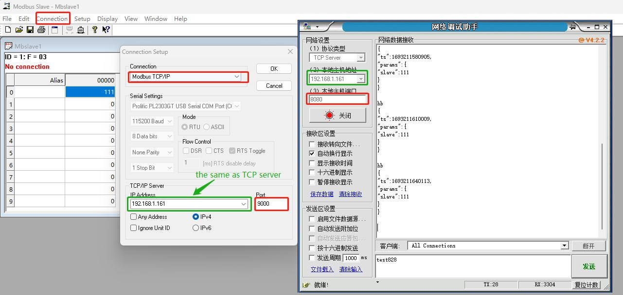
(5)After that, we can see the connection is established in the TCP Server.
The slave and TCP server start transmitting data.
- IO Setting
- Relay Setting
- Click IO Setting, and add a new Relay Channel, the parameters are set as follows:
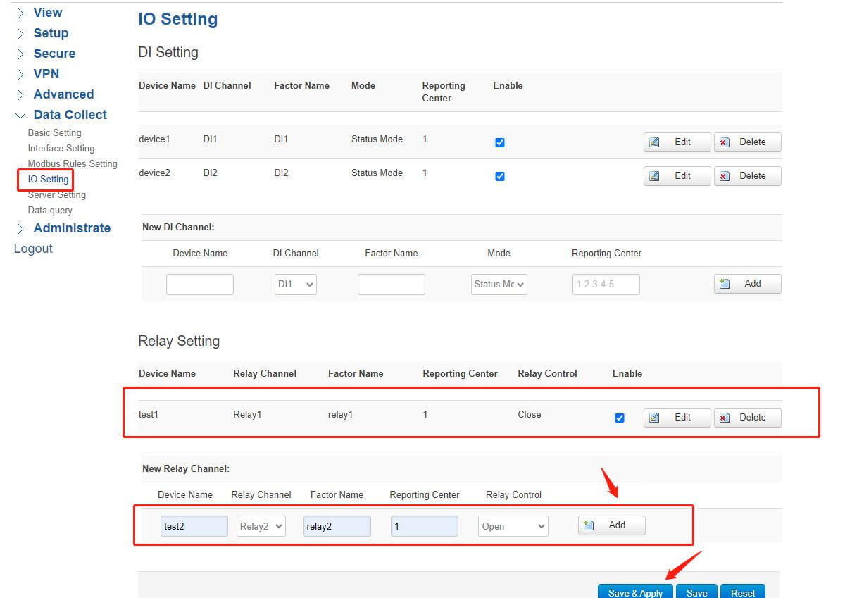
Device Name: The device name is set as you wish
Relay Channel: In relay interfaces, there are multiple channels available determined by a specific device
Factor Name: Corresponding report code of data collected
Reporting Center: data report center’s number
Relay Control: initial state of the relay, there are “open” and “close” two options
Once added, remember to click Save&Apply.
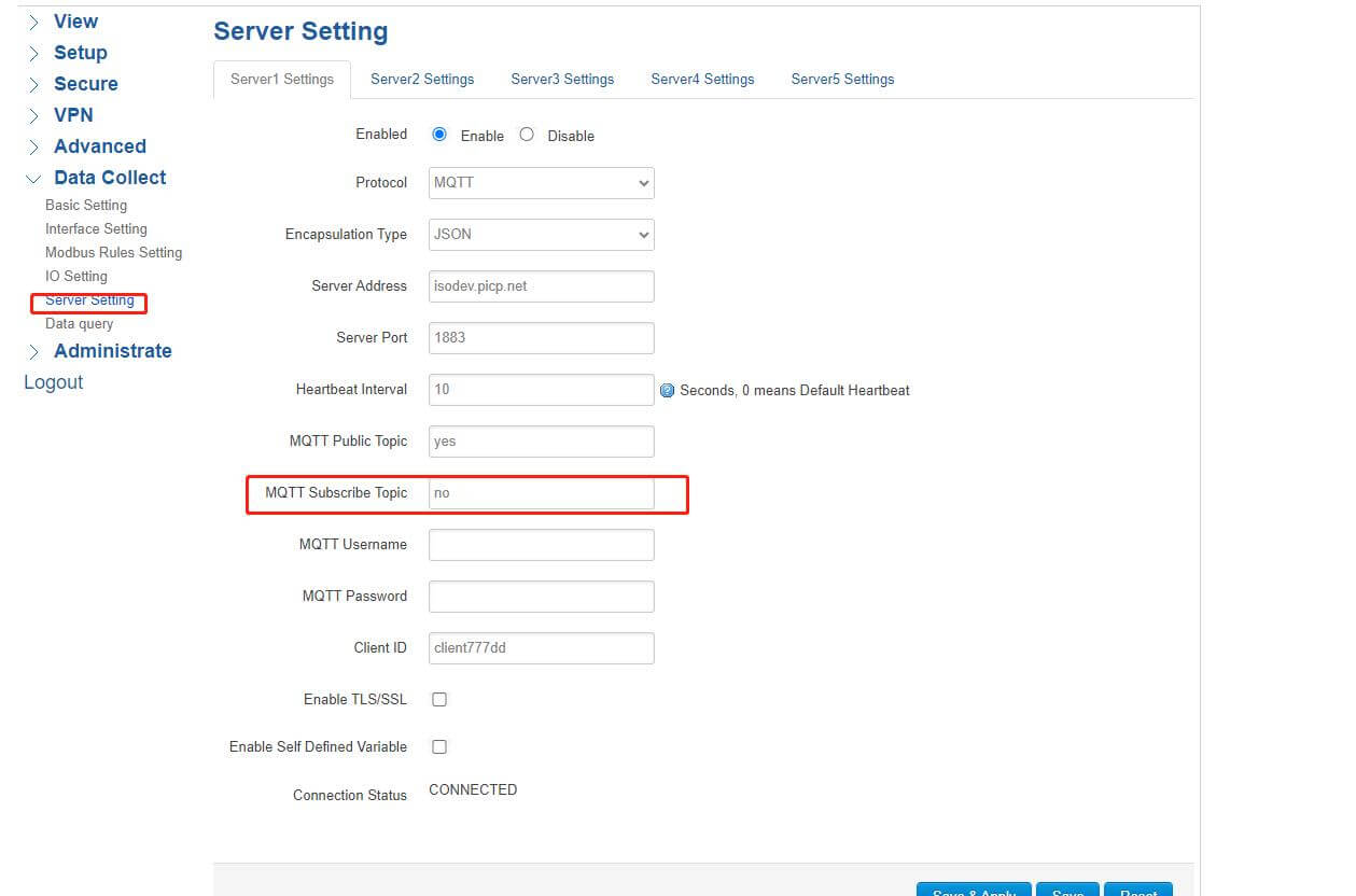
- Add an MQTT Subscribe Topic in the Server Setting, here I set “no”.
- Open MQTT.fx, and subscribe to the topic that is published in the MQTT Client, which will accept the initial state of relays.
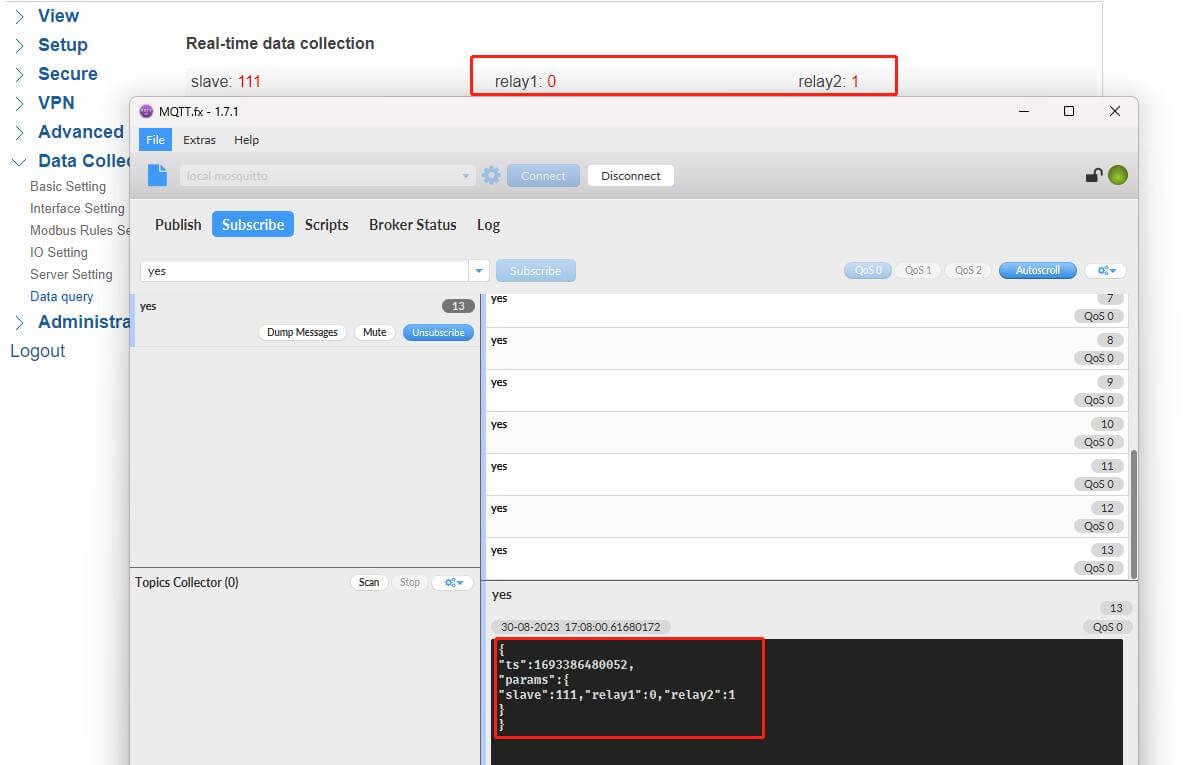
- RemoteControl Relay
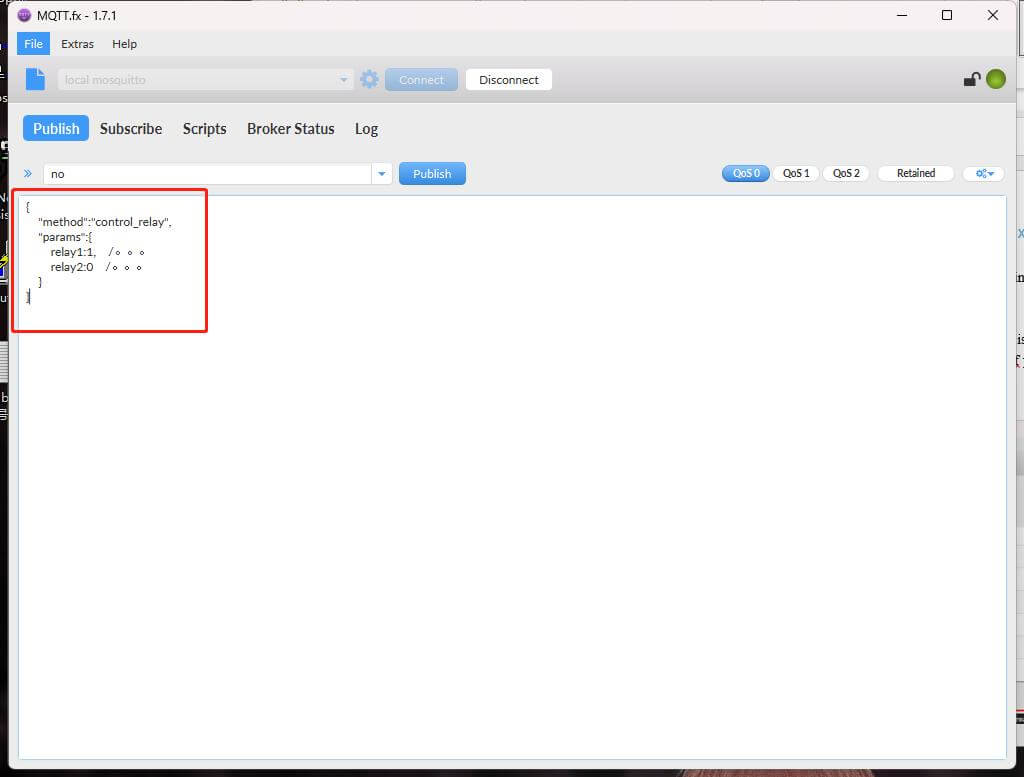
- If you want to control the relay’s state, you should publish the Subscribe Topic just set, and then issue the corresponding command.
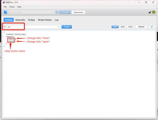
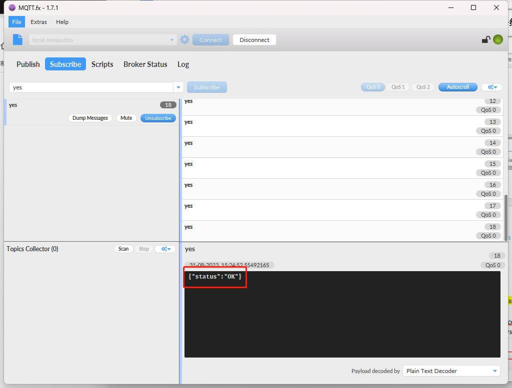
Then the gateway will respond with the status “OK”
After a while, you’ll see the relay’s state has changed successfully.
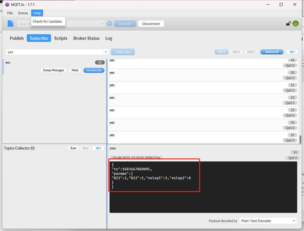
- If you do not modify successfully, you should check whether the corresponding interface is configured, or check the command format. Because the control command is in JSON format, if your command is incorrect, it will not be executed.
The gateway will respond like this:
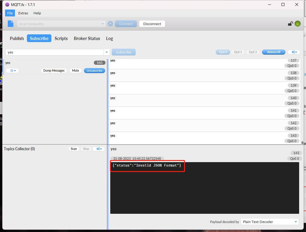
So before issuing the command, you have to change the corresponding control command into JSON format. This is very important.
You can try to issue different commands serval times to verify if the state of relays can be changed successfully.
- DI Setting
- Click IO Setting, you need to add a New DI Channel, the parameters are set as follows:
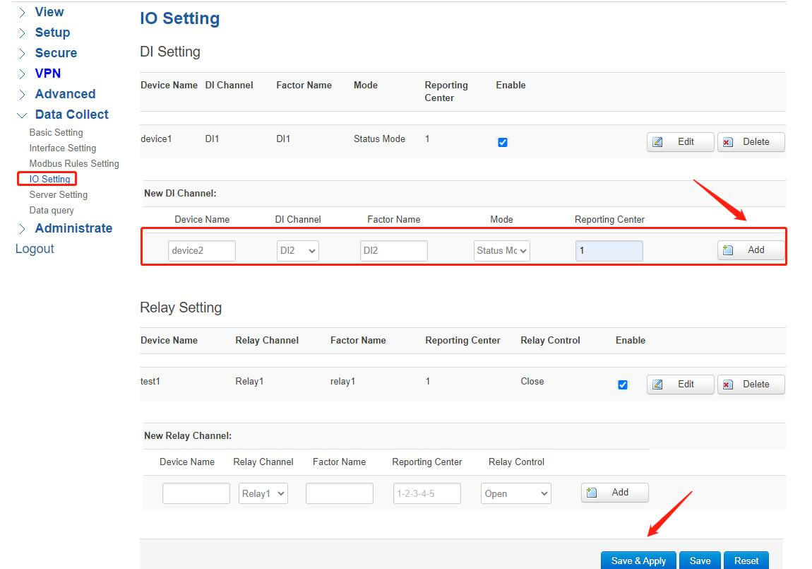
The other configurations are the same as the Relay Setting. Once added, remember to click Save&Apply.
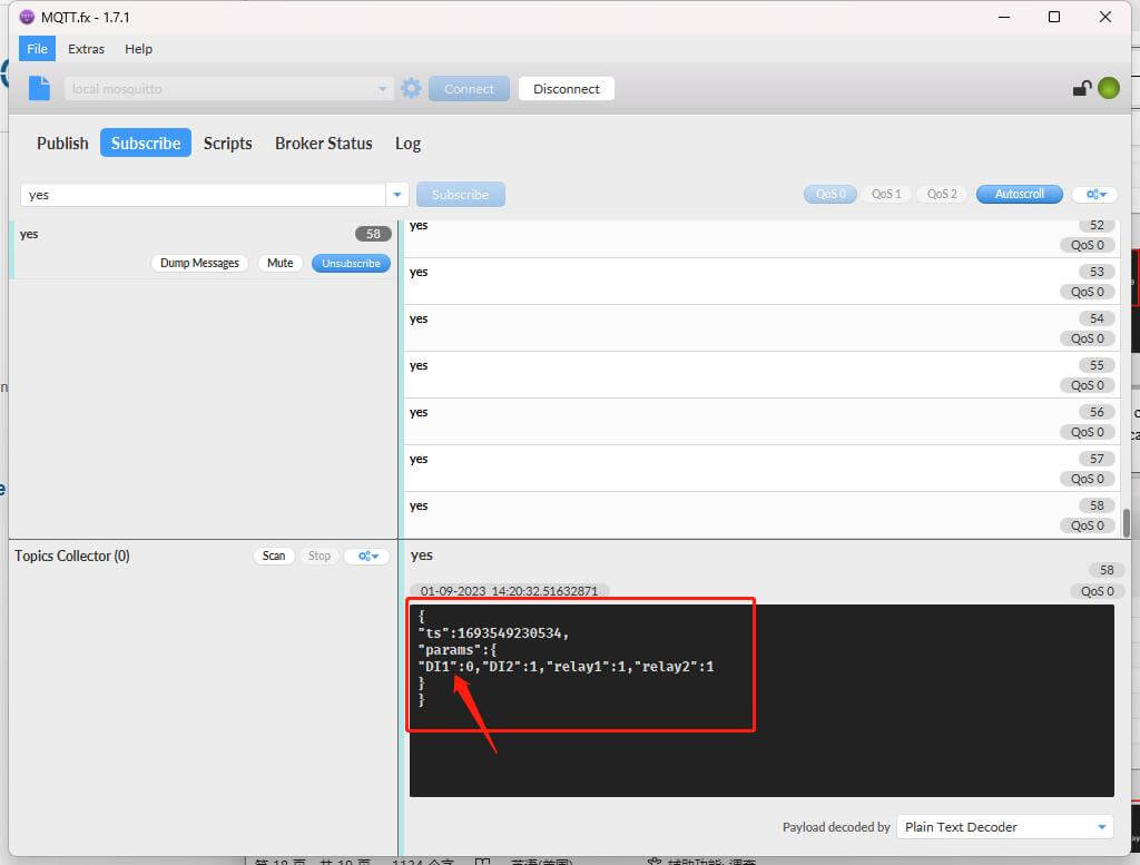
- Open MQTT.fx and subscribe to the public topic, then you can see the initial state of the DI port.
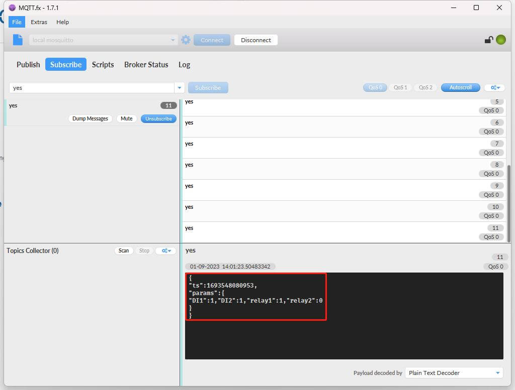
(3) If you want to change the DI’s state, you just need to short-circuit the “DI” port and the “GND” port. Then you’ll see the state of DI change immediately. You can try serval times to verify that.
- RemoteTelemetry Function
- Remote Telemetry Through MQTT
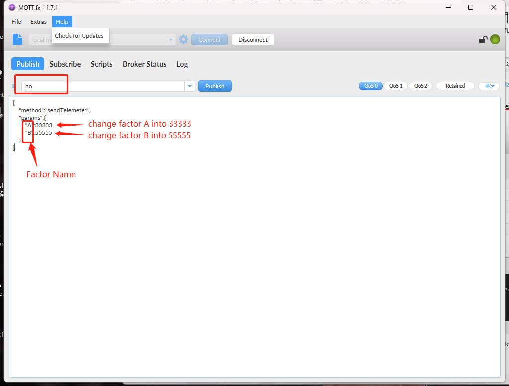
If you want to remotely modify the report factor’s value of the slave device, you should issue corresponding instructions through the MQTT Client or TCP Client. The command is also in JSON format. The specific steps are as follows:
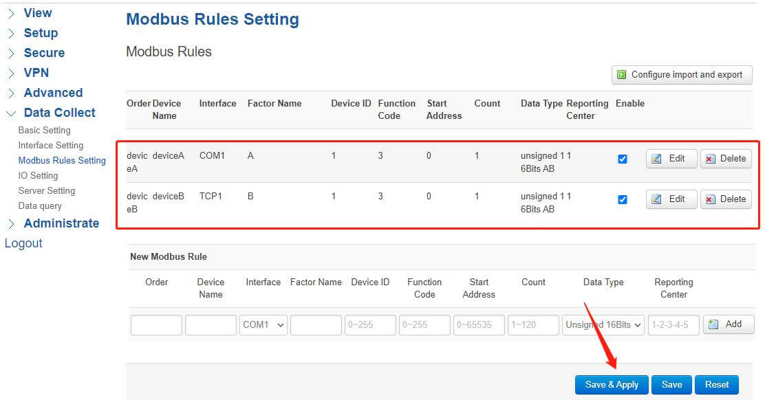
- Add Modbus Rules, the exact method is the same as before. Here I add two factors, “A” and “B”.Then click Save&Apply.
- Click Server Setting, the configuration is also the same as above.
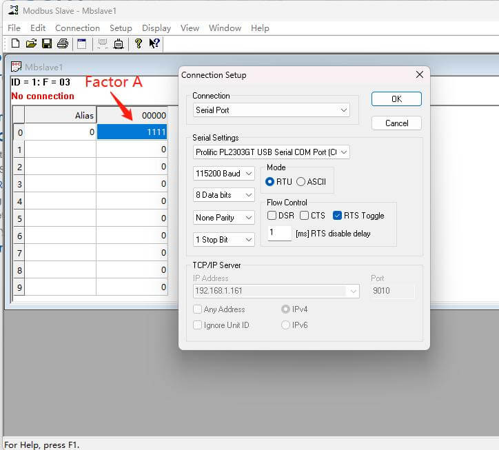
- Open Modbus Slave, and set initial values of two factors.
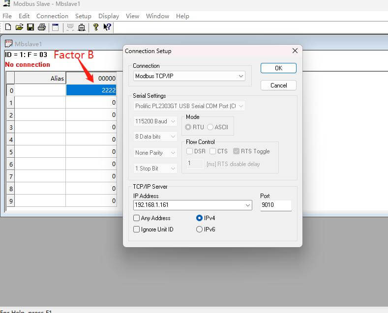
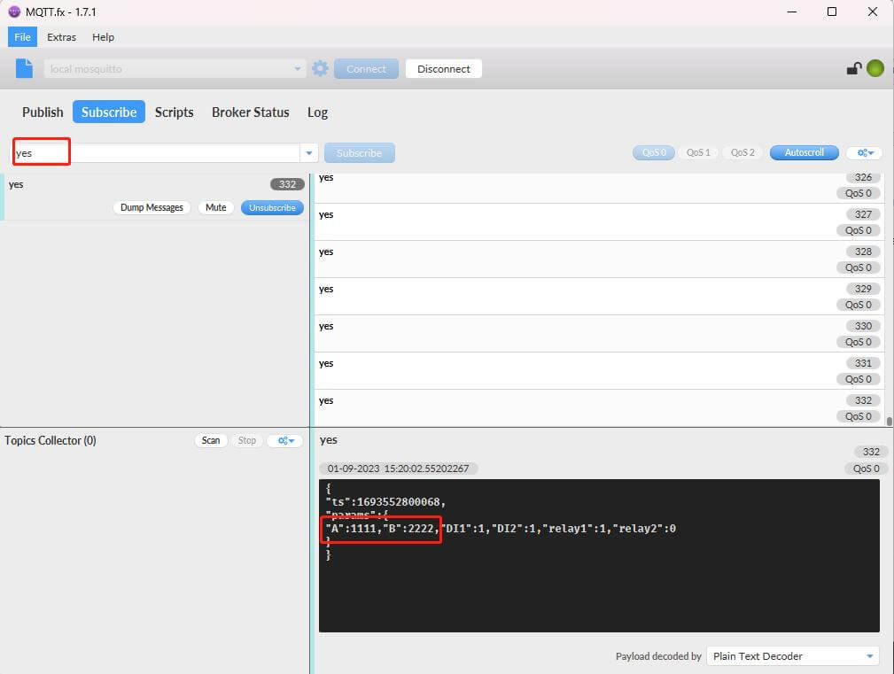
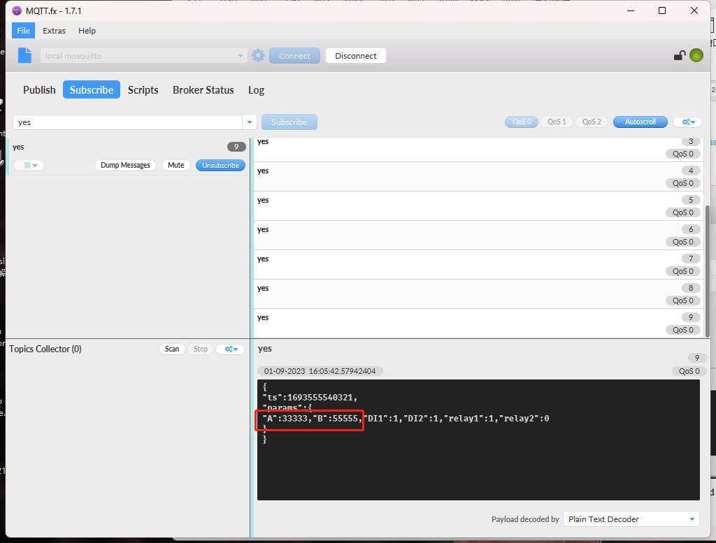
- Open MQTT.fx, and subscribe to the specific topic, then you can see the initial values of A and B.
- Publish the corresponding topic, and issue the command to modify the factor’s value, Pay attention to the command is also JSON format.
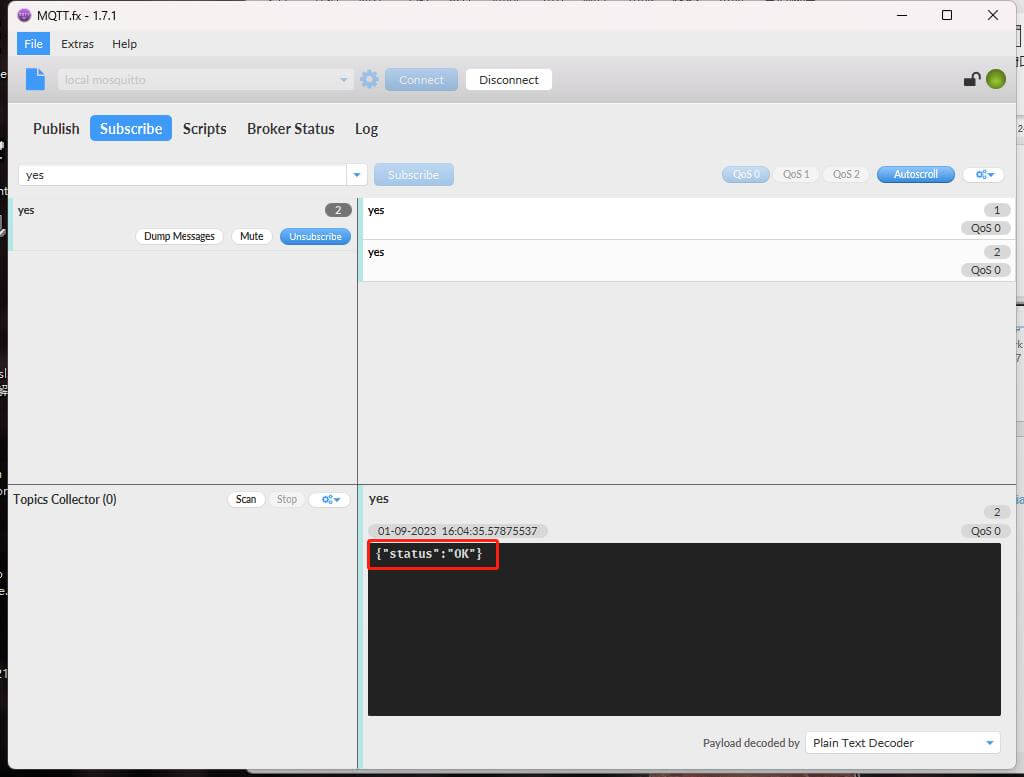
Then the gateway will respond to the status “OK”.
After a while, you’ll see the factor’s value has changed successfully.
- Remote Telemetry ThroughTCP
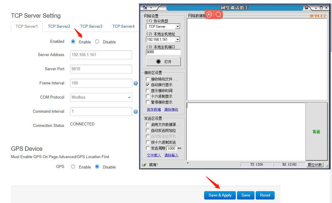
- Click Interface Setting, enable TCP Server, the configuration is the same as before, and click Save&Apply.
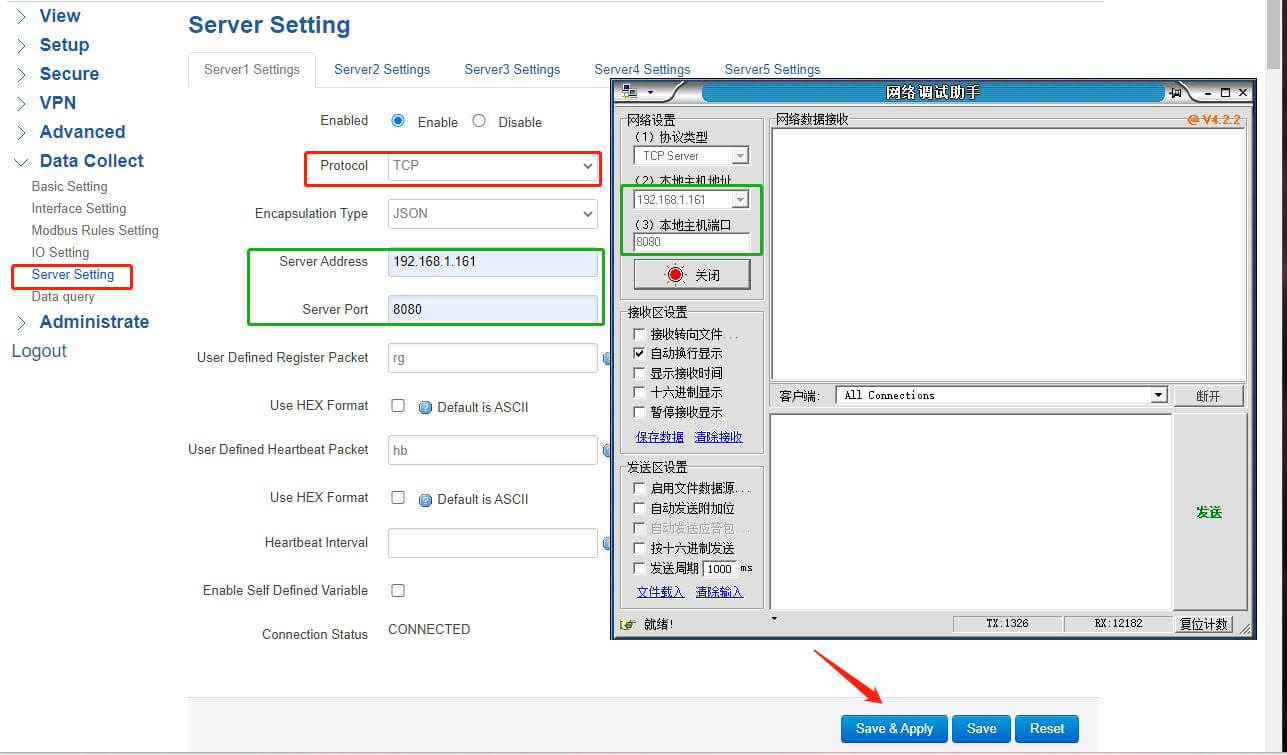
- Click Server Setting, change the Protocol to “TCP”, the Server Address and Server Port are the same as TCP Server, and click Save&Apply.
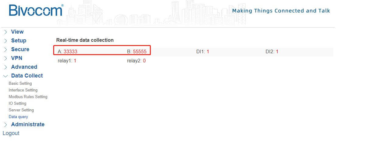
Then the TCP Server will accept the initial values of A and B.
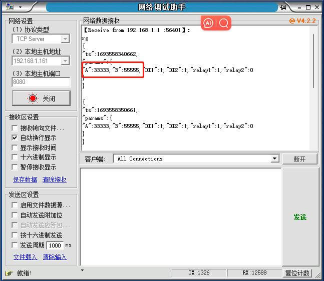
The WEBUI also can accept the data.
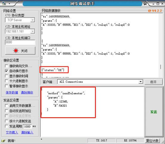
- Issue the corresponding command to modify the factor’s values as you wish. If the command is correct, the server will respond “status”: “OK” immediately.
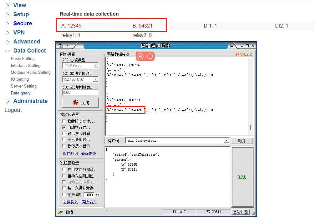
After a while, you’ll see the factor’s value has changed successfully.



1 Comment