How to Establish LoRa Communication between TG452&TW820
LoRa (Long Range) technology holds significant importance in today’s IoT (Internet of Things) landscape due to its ability to efficiently and cost-effectively connect and communicate with a wide array of sensors and devices over long distances. LoRa helps solve communication challenges by providing reliable connectivity in remote or challenging environments where traditional wireless technologies may struggle, such as Smart Agriculture, Smart Cities, Industrial IoT, Smart Home, etc.
Bivocom LoRa series product, LoRa gateway(TG452 LoRa), RTU(TG501 LoRa) and DTU(TW820) can be composed of different network structures to meet different applications’ requirements.
We will use 2xTW820 and 1xTG452 at this document to demo LoRa communication.
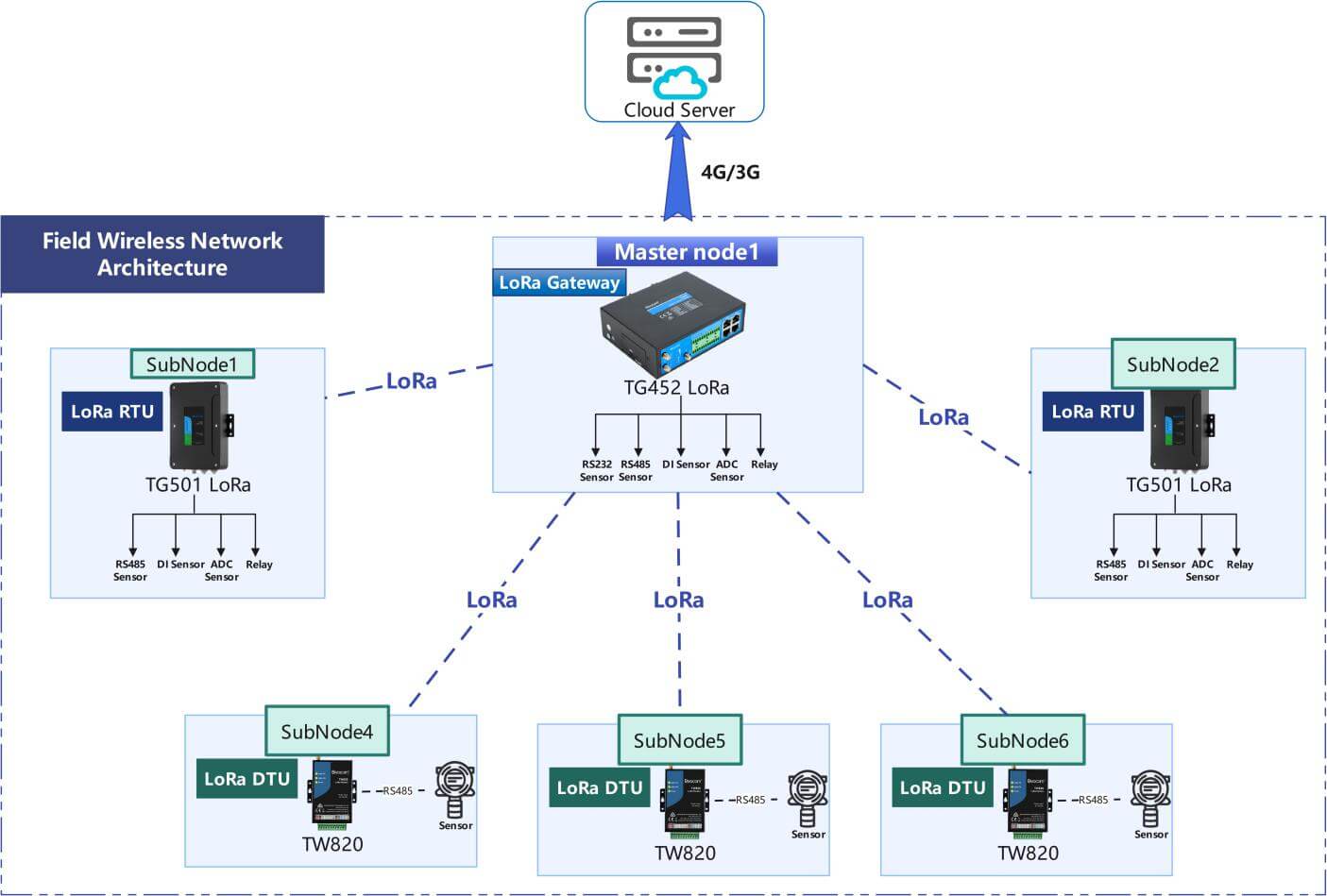
LoRa Application Topology
1. Configurations of TW820
- Enter Config Mode
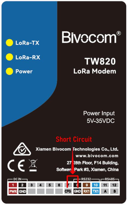
Connect TW820 and laptop with RS232 port(8,9,10), you will also need to Short-circuit CFG(7) and GND(8) with Dupont wire, then power on device(1,2).
- Read Parameters on Config Tool
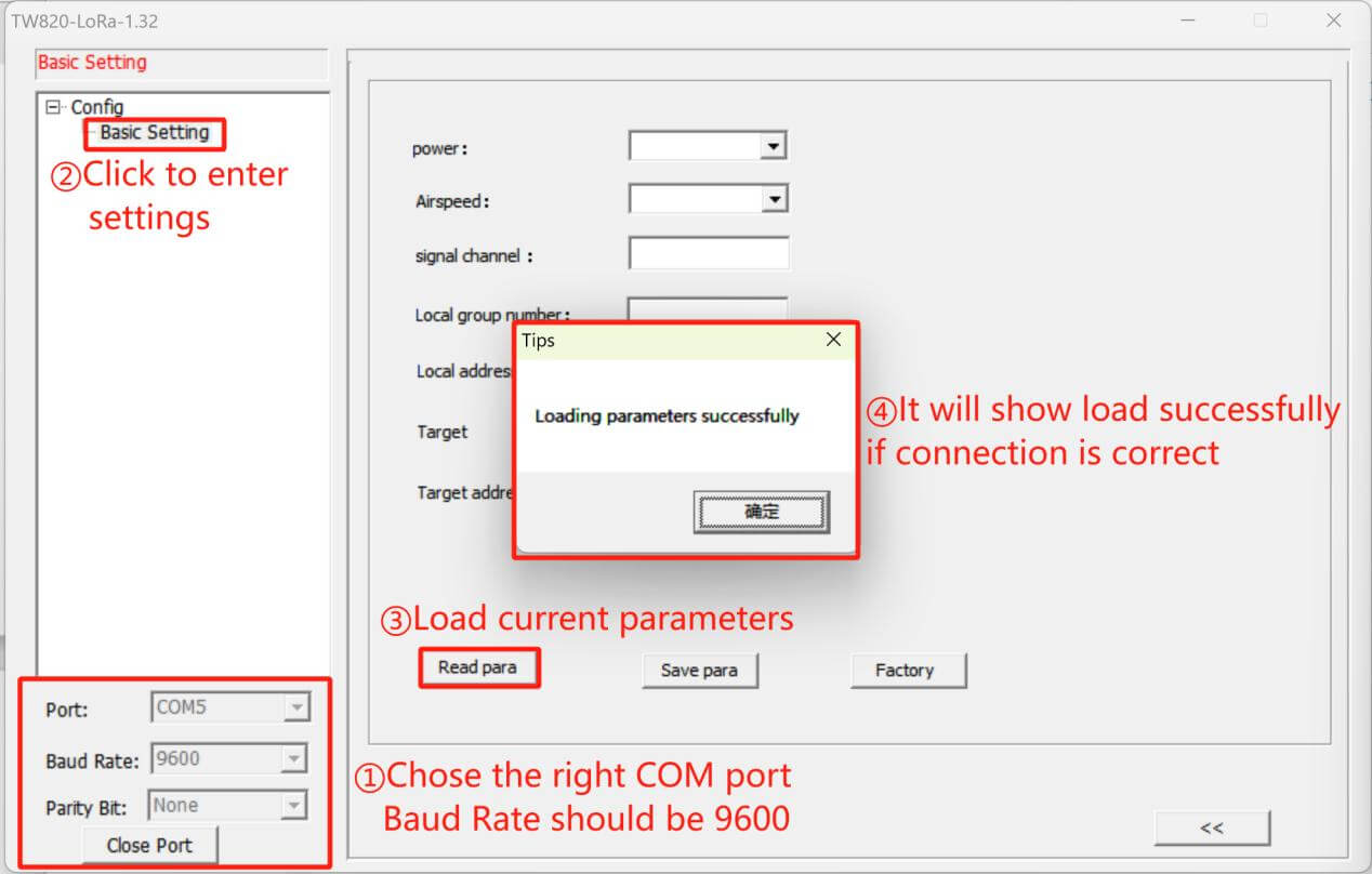
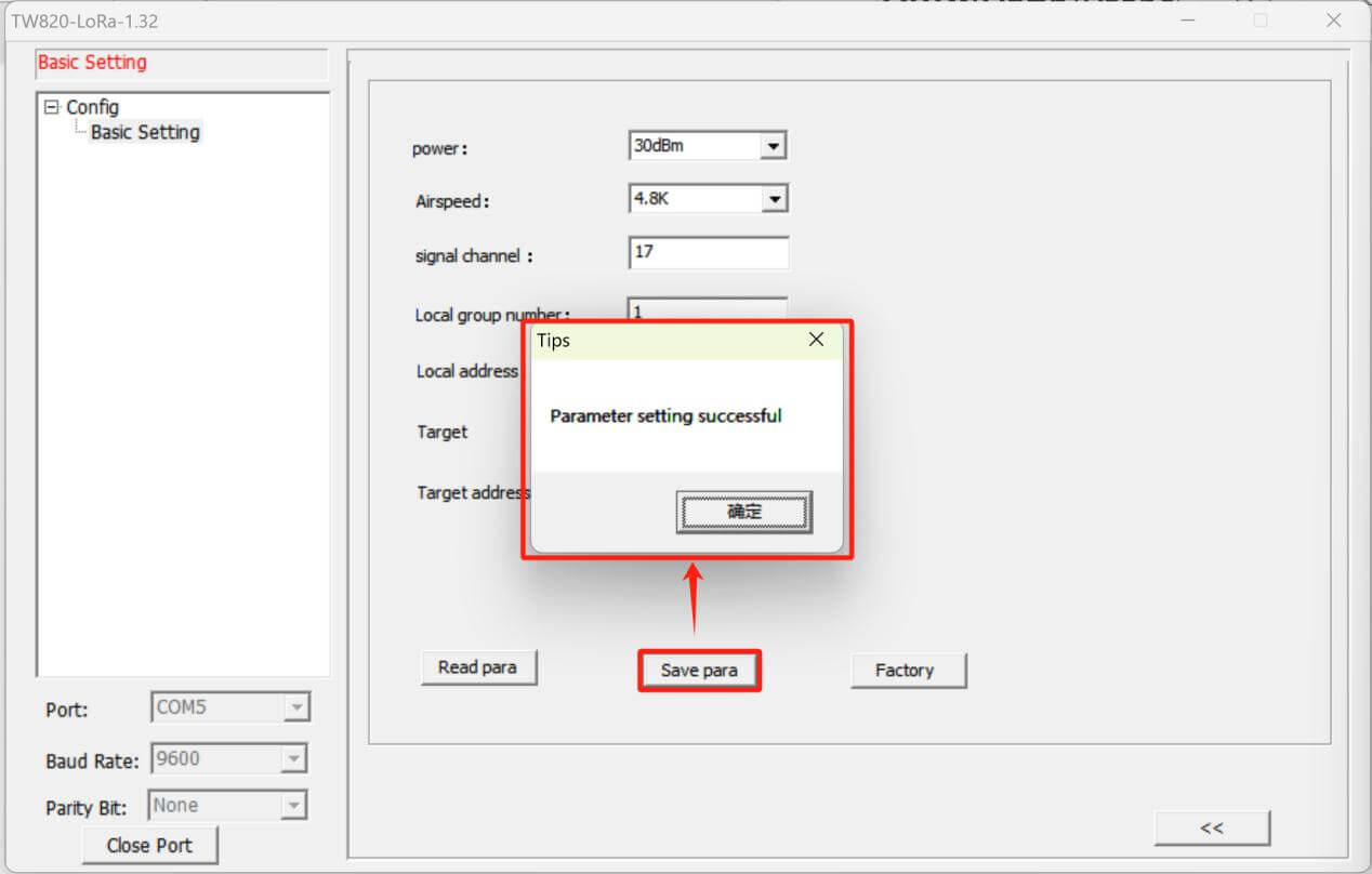
Open Config Tool(TW820-LoRa). After connect TW820 with laptop with RS232, you need to select the right COM port, baud rate need to be 9600. Click “Basic Setting” to enter configuration page, then click “Read Para” to load current settings, there will be a pop-up window to show load parameters successfully or failed.
- Change LoRa Parameters and Apply
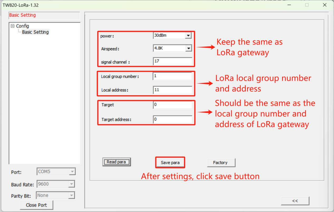
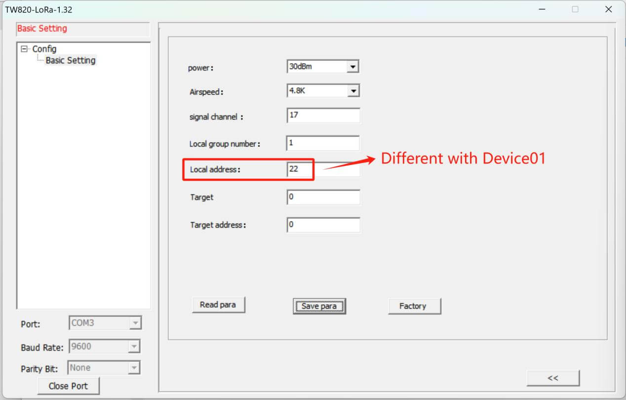
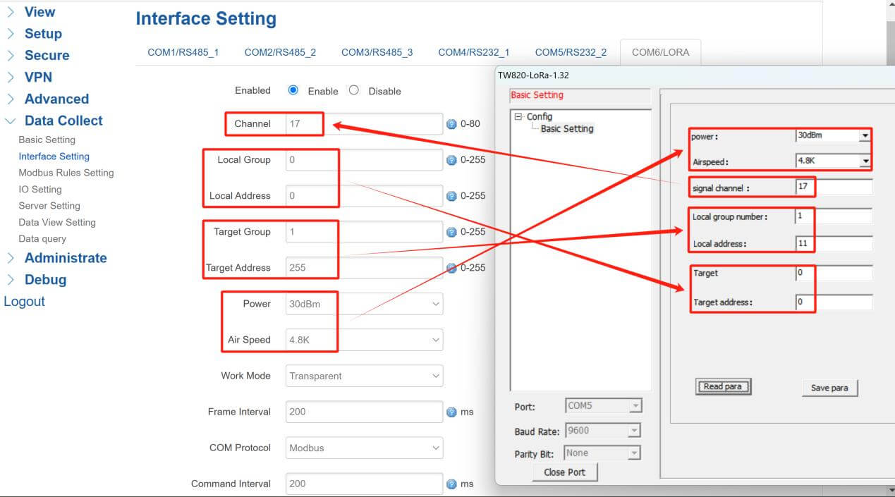
“Power”, “Airspeed” and “Signal Channel” should keep the same as LoRa gateway, if you have different TW820 to work as LoRa nodes, please keep “Local group” the same, and “Local Address” need to be unique for each TW820.
“Target ” and “Target address” should keep the same as LoRa gateway settings.
Click “Save para” after modify settings.
Device01(TW820):
Device02(TW820):
- Switch to Communicating Mode
Disconnect CFG((7) and GND(8), TW820 will switch to Communicating Mode. TW820 can support 1xRS232 and 1xRS485 communication.
2. Configurations of TG452 LoRa Gateway(Modbus Mode)
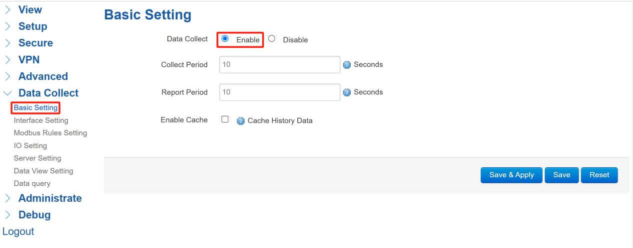
- Basic Setting
“Collect Period” defined the interval of data collection, “Report Period” will be the interval of reporting to Servers.
- LoRa Interface Settings
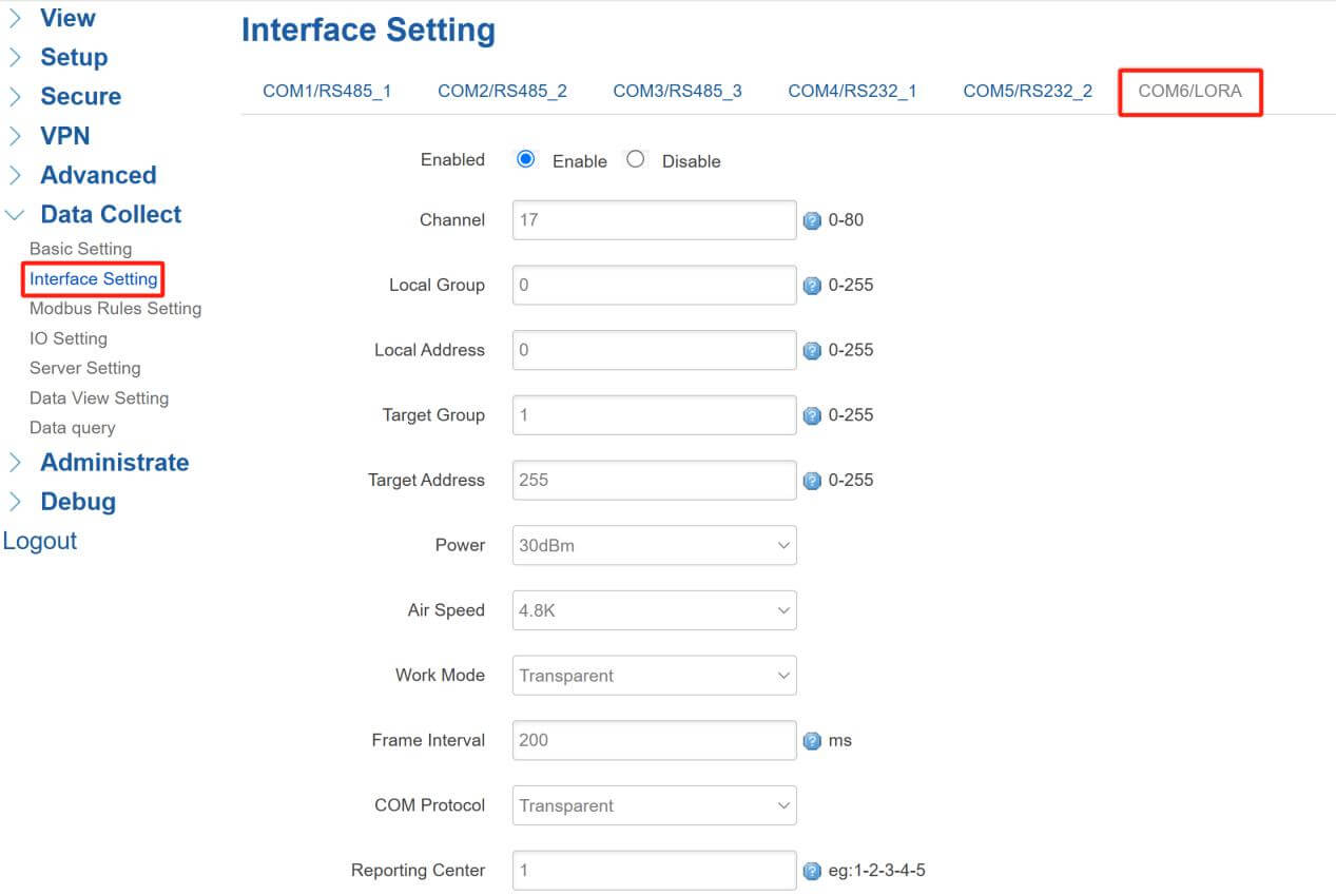
Enter Interface Setting page, click COM6/LORA to set the parameters:
“Channel” needs to be the same as other TW820 LoRa nodes.
“Local Group”&“Local Address” will be the target marks of other TW820 LoRa nodes, here we keep the same as previous setting of TW820, set them as 0,0.
“Target Group” will be the same as the local group of TW820 LoRa nodes.
“Target Address”, when target address is “255”, it means enable broadcast transmission to every address in current group “0”, any address in current group “0” can receive the data.
“Power” defined the power of LoRa module.
“Air Speed” needs to keep the same as TW820 LoRa nodes, so set “4.8k”.
“Work Mode” of LoRa is transparent, so data won’t be encapsulated by any protocol.
“Frame Interval” should set at least 200ms because of LoRa transmission rate limit.
“COM Protocol” has two options, “Transparent” means data will directly transmit to servers, if set “Modbus”, this COM6 can work as other serial port like RS485 to communicate with different sensors.
“Reporting Center”: When “Transparent” mode is enabled, you should set the corresponding server, different servers’ number separated by minus “-”.
Don’t forget to click “Save&Apply” after modify settings.
- Modbus Rules Setting
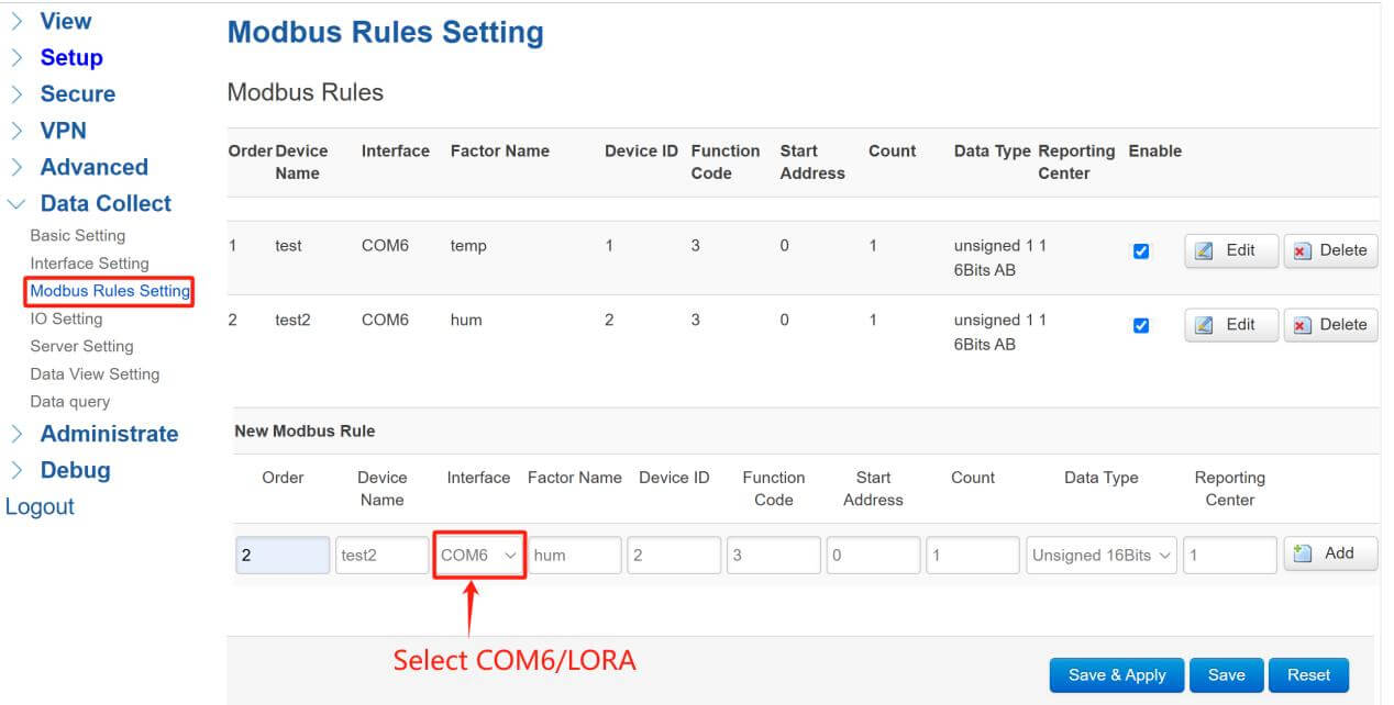
If enabled “Modbus” for “COM Protocol”, we can set Mobus Rules to read data from the sensors connect with LoRa nodes on field wirelessly.
“Interface” needs to select COM6/LORA, this is the interface of LoRa data input and output.
“Factor Name ” will be the name of data collected when reporting to server, here I set them as “temp” and “hum”.
“Device ID”, “Function Code”, “Start Address”, “Count” and “Data Type” should follow the data sheet of sensors connect with LoRa nodes on field.
At this case, I set 2 different Modbus Rules to collect 2 different sensors’ data and report to TCP server.

- ModbuSlave Setting
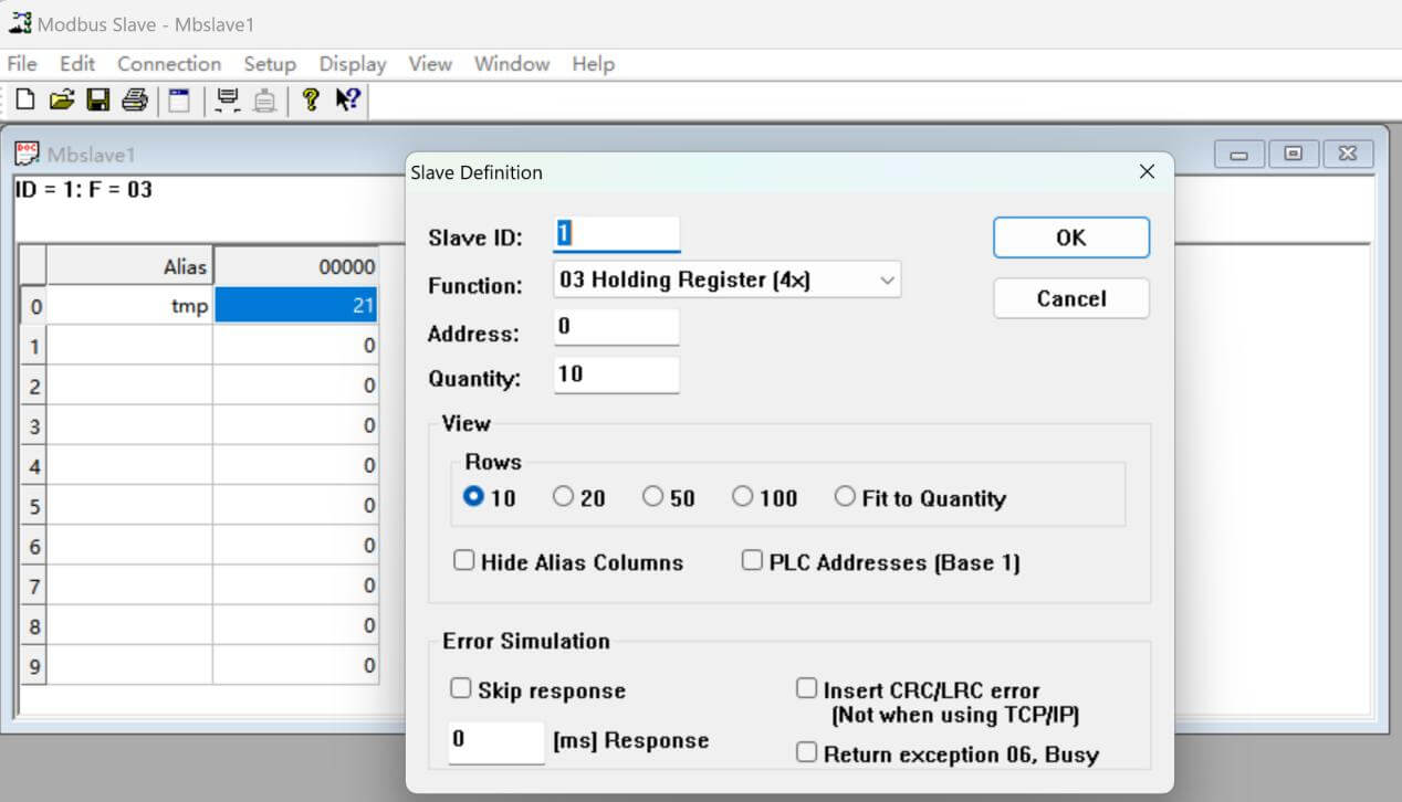
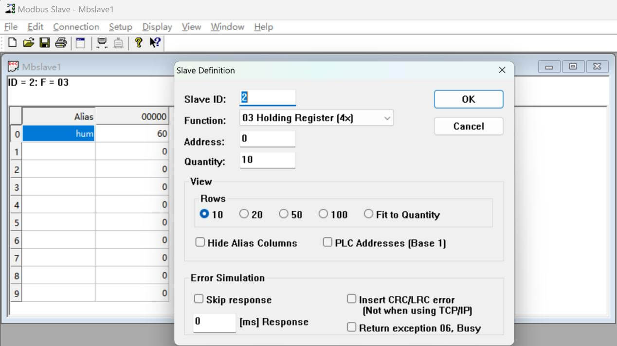
At this case, I use Modbus Slave to simulate field sensors which connect with TW820 LoRa nodes.
Sensor01:
Sensor02:
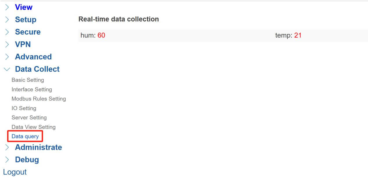
- Data Query
At “Data query” page, we can see the real-time data here:
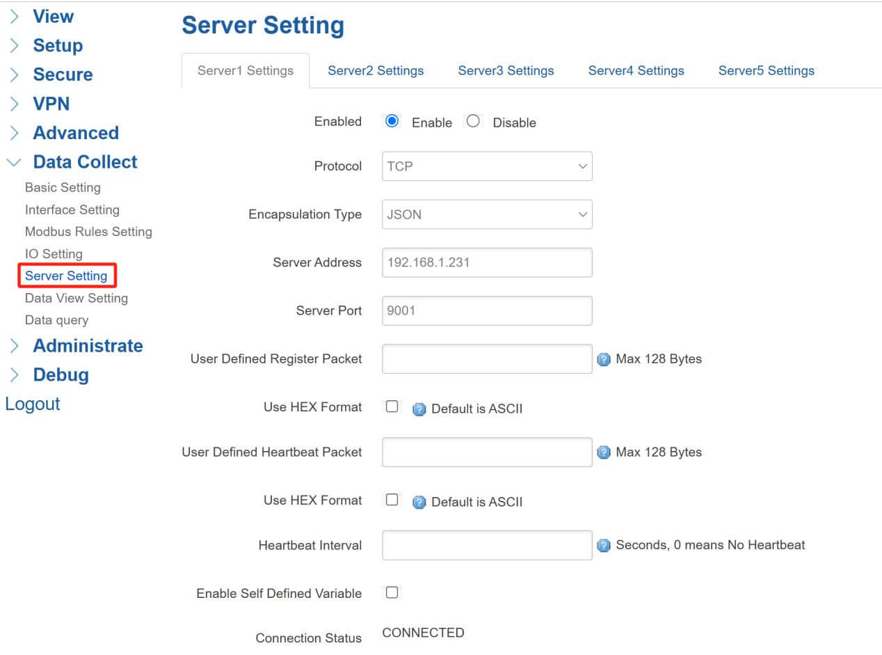
- Server Setting
TG452 can send data to different types of server, I set TCP server for receiving the Modbus sensors’ data.
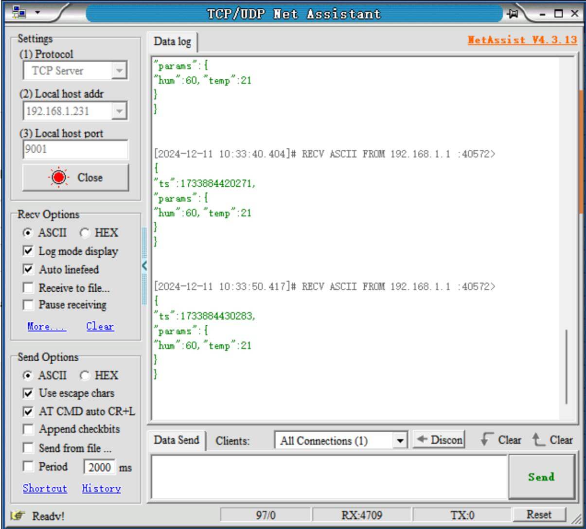
- Data Reporting
- TCP Server(NetAssist)
After all settings, TCP server can receive the field sensors’ data.
- Transparent Mode
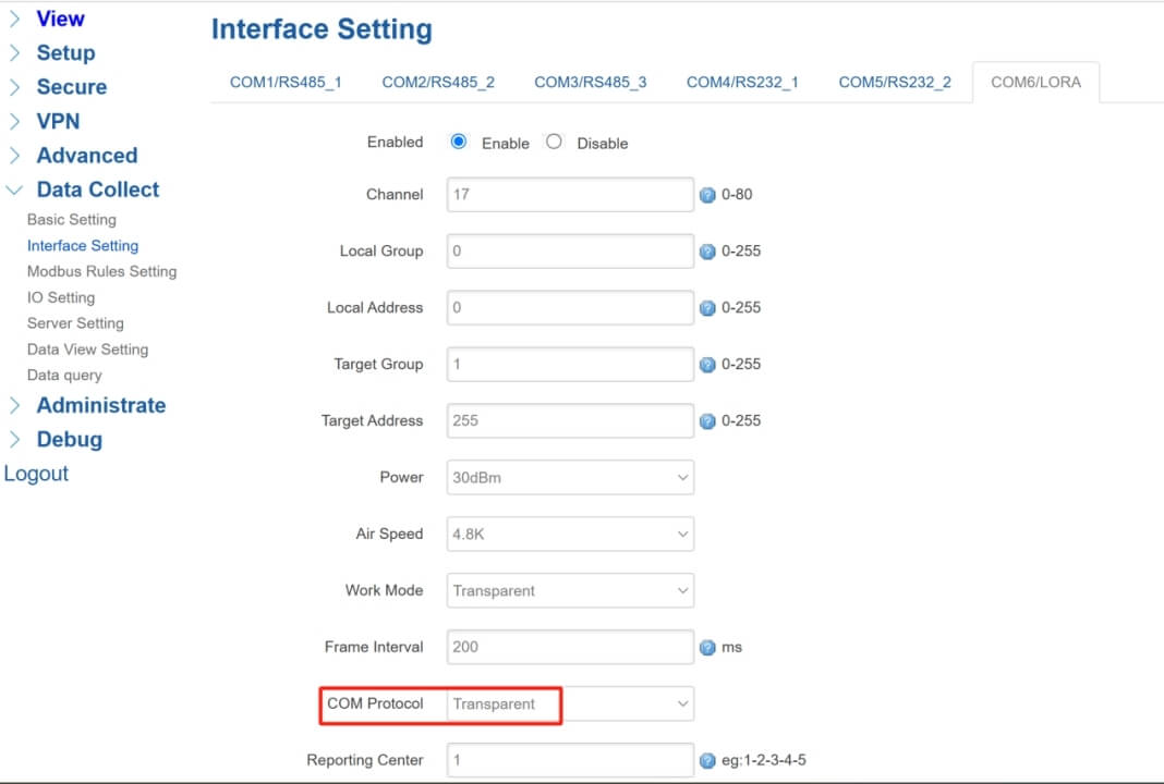
We can also enable transparent mode for LoRa gateway, that means TG452 will transmit original data to TW820 LoRa nodes directly.
- Interface Setting(TG452)
“COM Protocol” should set “Transparent” at this mode.
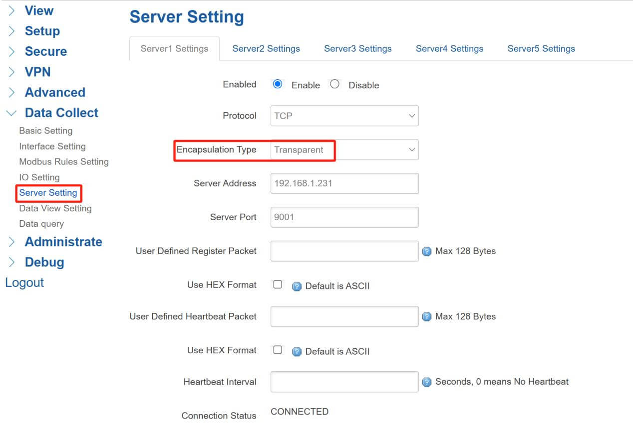
- Server Setting
“Encapsulation Type” needs to be “Transparent” too.
- Test Result
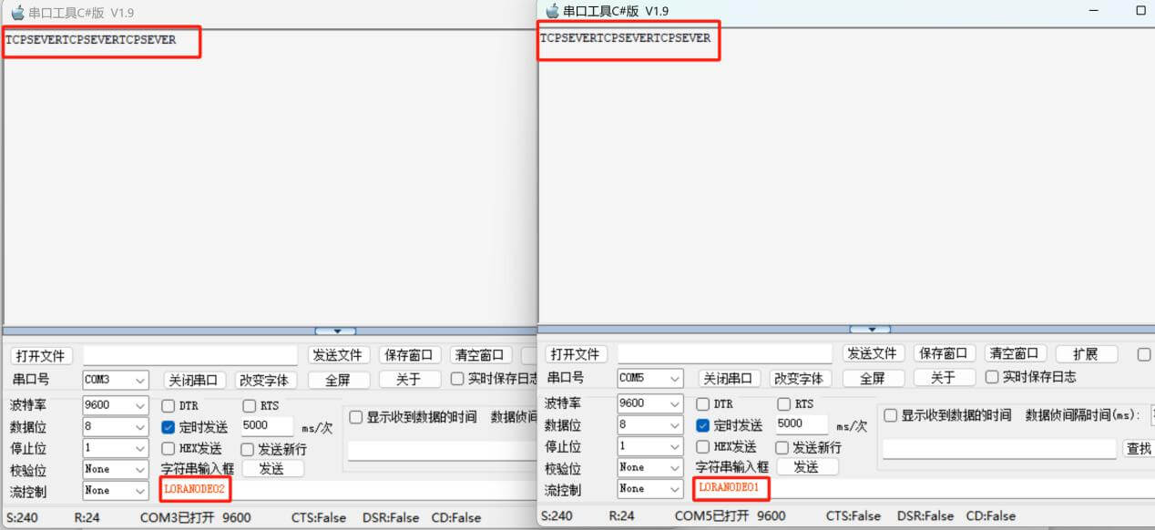
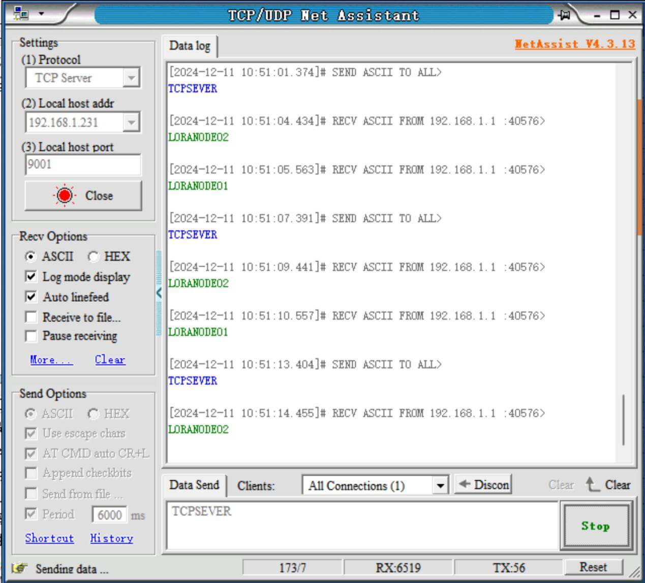
Use 2 serial port tool to send different data “LORANODE01” and “LORANODE02” every 5s.
At TCP Net Assistant, I also enabled data “TCPSERVER” sending every 6s.
We can see the data displayed as bellow:
Related video: https://www.youtube.com/watch?v=k27AWsI-hMc&t=204s



Comment