In this article, we’ll show you how to enable serial ports(RS232, RS485) and get serial data from Bivocom IoT router. All Bivocom Routers TR321 and TR341, and gateways TG451, TG452, TG453, TG462, TG463 comes with serial ports, so the guide is applicable to all these models unless the RS232 is used as debug port.
What You Need?
- Bivocom Router TR321
- TCP/UDP Net Assistant(To simulate a TCP server)
- Bivocom config tool of TD210(to simulate a sensor to generate data)
1. RS232 or RS485 Cable Wiring
All of Bivocom routes’ serial port are designed with industrial terminal block interface, you can finish the cable wiring as below.
RS232 cable wiring: Blue—TX, Brown—RX, Black–GND
RS485 cable wiring: Red–A, Black—B
2. Configuration on Web GUI page
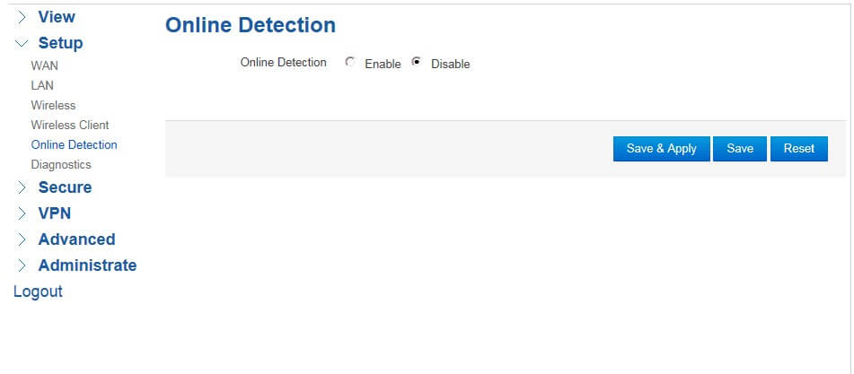
2.1 Disable online detection
If Bivocom router is dialed up via wired cable, but without SIM card, please disable the online detection before the testing. See as the detail following operation. You can go to next step if you’re using 4G/LTE.
- Click “Setup”–”Online Detection”, and then select “Disable”
- Click “Save & Apply” for configuration to take effect.
2.2 Serial communication configuration
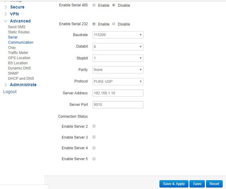
RS232 communication configuration
- Click “Advanced”–”Serial Communication”, select “Enable” of “Enable Serial 232”
- Type in the relative parameters of baud rate, data bit, stop bit, parity according to your sensors or devices’ parameters.
- Select the relative protocol from “PURE UDP”, “PURE TCP”, “Self Defined TCP”, “FTCP”, “HTCP”, “HUDP”, “TCP Sever”, “Modbus TCP”, “Modbus RTU”, “HTTP Client”, “MQTT”.
- Type in other additional parameters on the page once you select some protocols.
- Click “Save & Apply” for configuration to take effect.
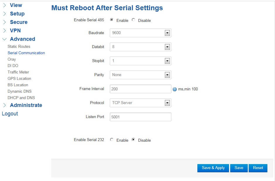
RS485 communication configuration
- Click “Advanced”–”Serial Communication”, select “Enable” of “Enable Serial 485”
- Type in the relative parameters of baud rate, data bit, stop bit, parity according to your sensors or devices’ parameters.
- Select the relative protocol from “PURE UDP”, “PURE TCP”, “Self Defined TCP”, “FTCP”, “HTCP”, “HUDP”, “TCP Sever”, “Modbus TCP”, “Modbus RTU”, “HTTP Client”, “MQTT”.
- Type in other additional parameters on the page once you select some protocols.
- Click “Save & Apply” for configuration to take effect.
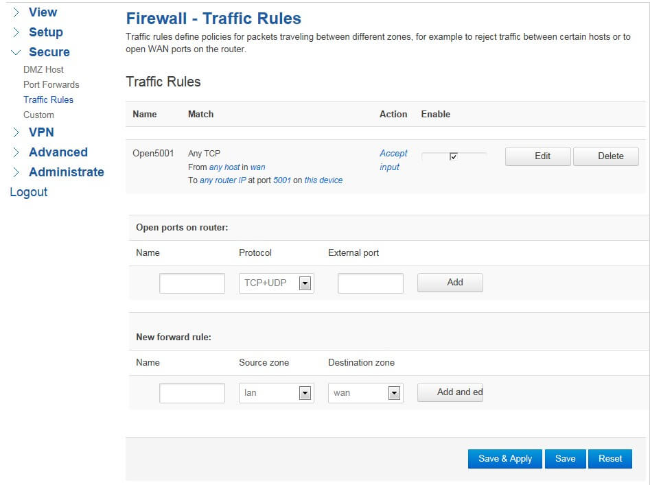
2.3 Traffic rules configuration
Click “Secure”–”Traffic Rules”, and then go to “Open ports on router”, and type in the relative “Name”, “Protocol”, and “External port”. Then click “Add”, and “Save & Apply” for configuration to take effect.
3. Debug Testing via Data Software.
Hereby take the debug testing via “TCP/UDP Net Assistant” (can be valued as data server software) as an example.
3.1 TCP server configuration
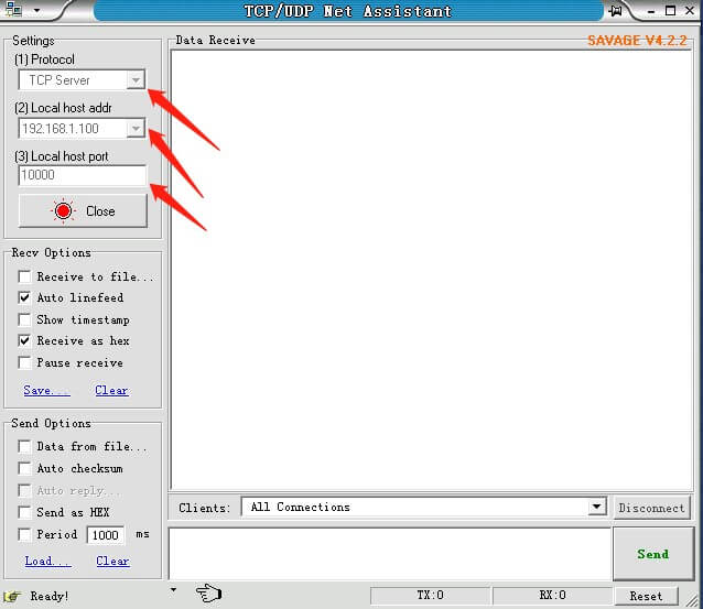
1) Running ” TCP/UDP Net Assistant”, select “TCP Server” from “Protocol”, type “Local host addr” with 192.168.1.100, type “Local host port” with 10000.
2) Click “Open” to enable a virtual local TCP server.
3.2 Serial communication configuration on Web GUI page
Go to Bivocom local Web GUI page, and enable serial port. Hereby take RS485 as an example.
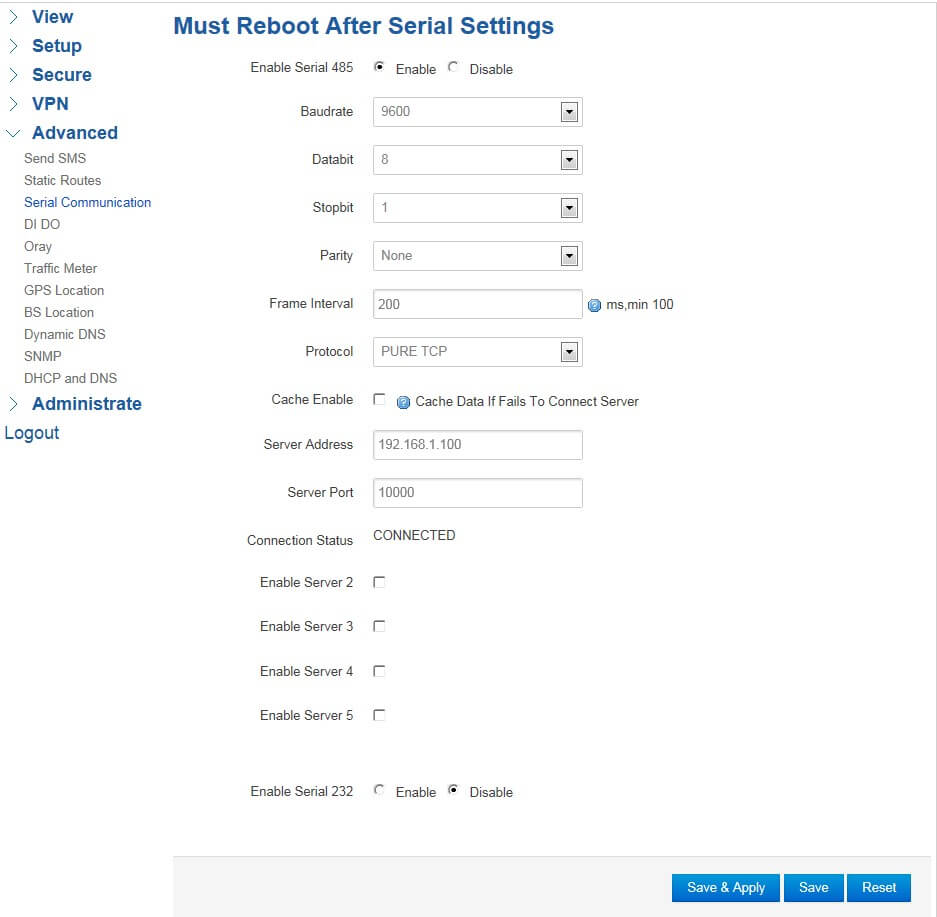
- Click “Advanced”–”Serial Communication”, select “Enable” of “Enable Serial 485”.
- Set Baudrate as “9600”, Databit as “8”, Stopbit as “1”, Parity as “None”, Frame interval as “200ms”
- Select “PURE TCP” protocol.
- Set “Server Address” as “192.168.1.100”, “Serial Port” as “10000”.
- Click “Save & Apply” for configuration to take effect.
- Then you will find the “Connection Status” will be “CONNECTED”. That means the connection between Bivocom router and virtual local TCP server has been established successfully.
3.3 Verification serial communication
We would like to introduce “Serial Port Debug Tool” here to finish this simulation testing, which will play for a role of kinds of PLC/sensors.
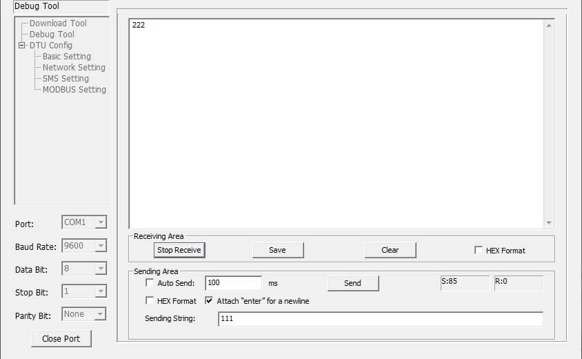
- Running a local “Serial Port Debug Tool” on your PC, and do following configuration.
- Select “COM1” or the other one of “Port”. Please ensure “COM1” or any one serial port has been open on your PC side!
- Set “Baud Rate” as “9600”, Databit as “8”, Stopbit as “1”, Parity as “None”.
- Click “Open Port”
Data communication verify
- Type” 111” at the “Sending String” area on “Serial Port Debug Tool”.
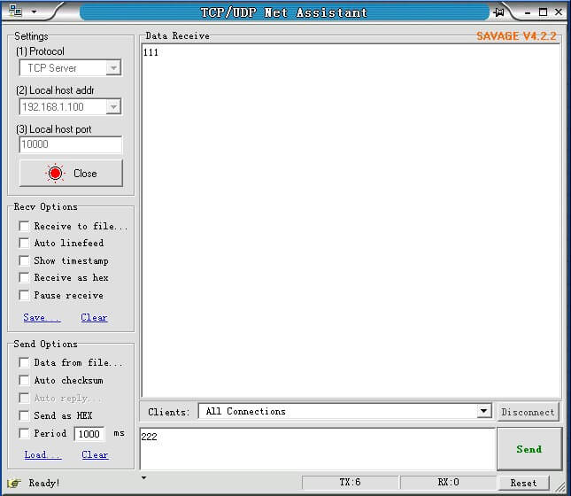
- Check if the “Data Receive” area of “TCP/UDP Net Assistant” get “111” string too.
- Type ” 222” at the “Sending” area on “TCP/UDP Net Assistant”, and click “Sending”.
- Check if the “Receiving Area” of “Serial Port Debug Tool” get “222” string too.




1 Comment